Safe-modding a C64 PSU with a USB charger
In this post an original wedge shape Commodore 64 PSU is modified with a USB charger to make it safe to use. Otherwise there is a risk of it failing and damaging the computer.
The power supply has a 5V DC and a 9V AC output. The 5V output is unreliable and has a tendency to fail by delivering a much too high voltage that will fry circuits in the C64. In this modification the 5V is replaced by a modern switching supply taken from a USB charger. The 9V AC output remains original.
Alternatives
There are great aftermarket C64 PSUs being produced today, and there are overvoltage saver cables made for saving the computer in the event of a PSU that goes bad. Each solution has its advantages and disadvantages. Using a new PSU is definitely the safest and most reliable solution, but it doesn't look very original. Using an overvoltage saver cable will save the C64, but it will not improve the original PSU. It will still run very hot and eventually break.
With this solution, it's possible to run the computer with a fully original looking PSU that won't go bad and won't run very hot (assuming a high quality USB charger was used for the modification).
The mod
Disclaimer! The modification involves working with mains voltage. Do so at your own risk and only if qualified.
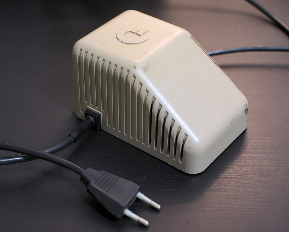
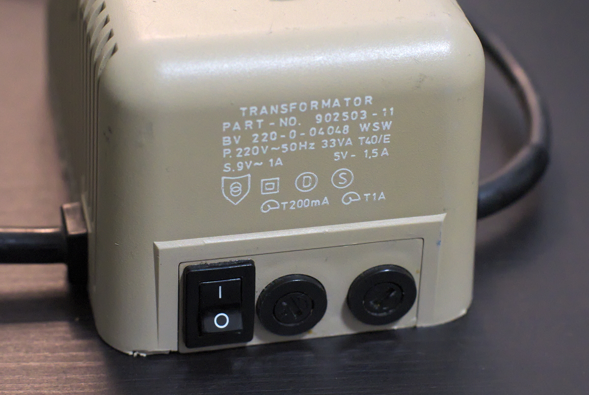
The PSU to be modified is from 1986 and was bought in Denmark. It's a wedge style, double fused version with a switch:
I managed to pry off the bottom plate with a lot of force. It was not an easy task. The plastic had to be broken off of the studs and the L shaped piece in the middle.
With the bottom off we can see the internals. The PCB responsible for regulating the 5V output is not potted with epoxy and is easily accessible. This is not the case with other common C64 PSU bricks. Notice the darkened areas on the PCB:
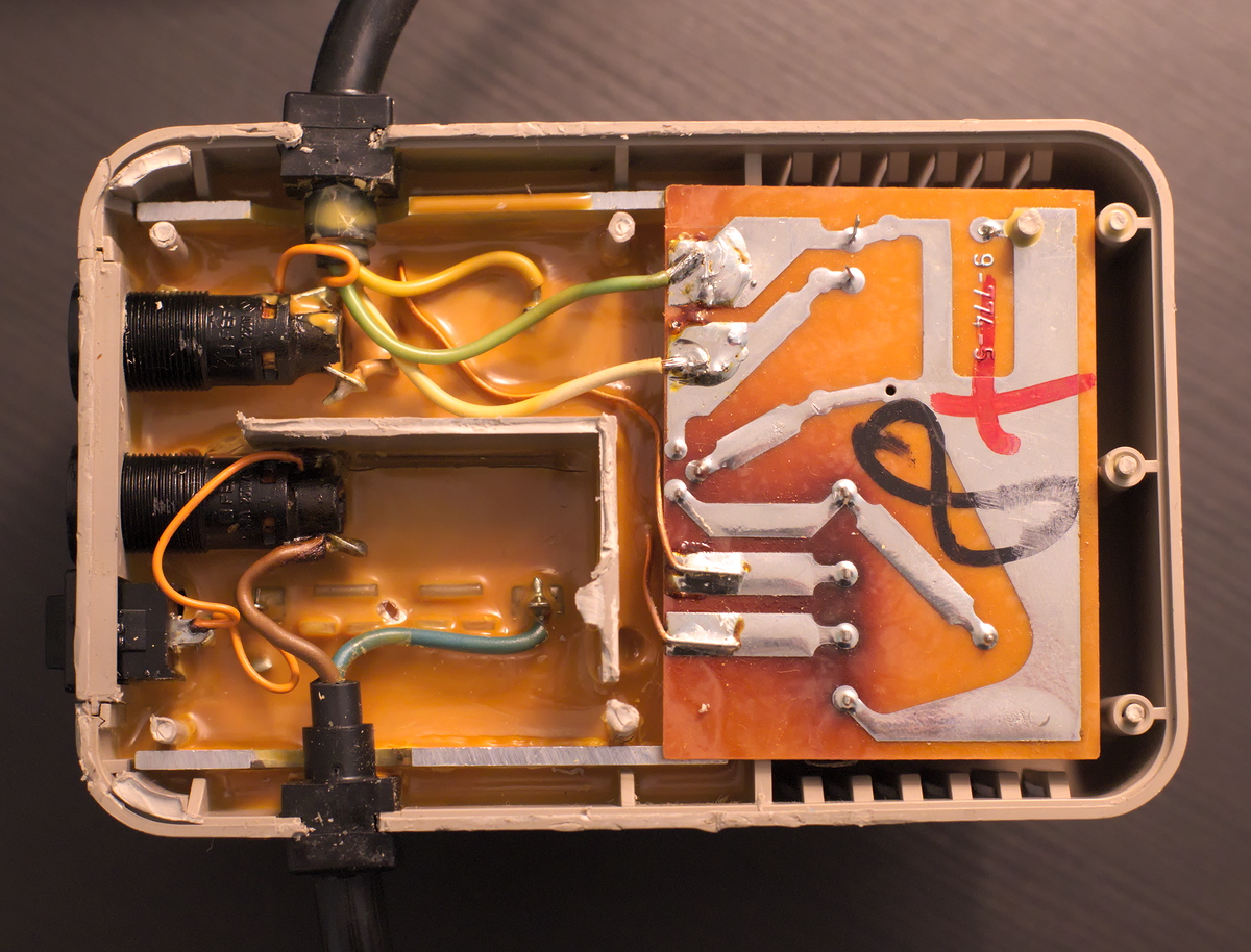
I connected a C64 while measuring the 5V voltage. It turned out to be totally fine. The PSU is not defective at this point.
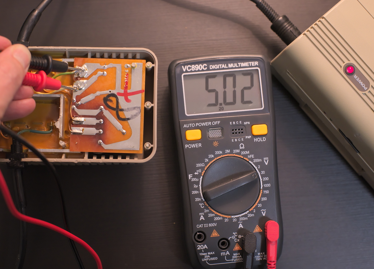
However, according to the wisdom of the internets, it will fail at some point generating a too high voltage on the 5V output. I believe this to be true. The PSU uses linear regulation for the 5V that generates a lot of heat which can't be dissapated very well. After cooking itself long enough, the voltage regulator may fail in a way that delivers an unregulated voltage on the 5V output, spelling doom.
The idea of this modification is to get rid of the old 5V circuit and replace it with the internals of a USB charger.
The donor USB charger:
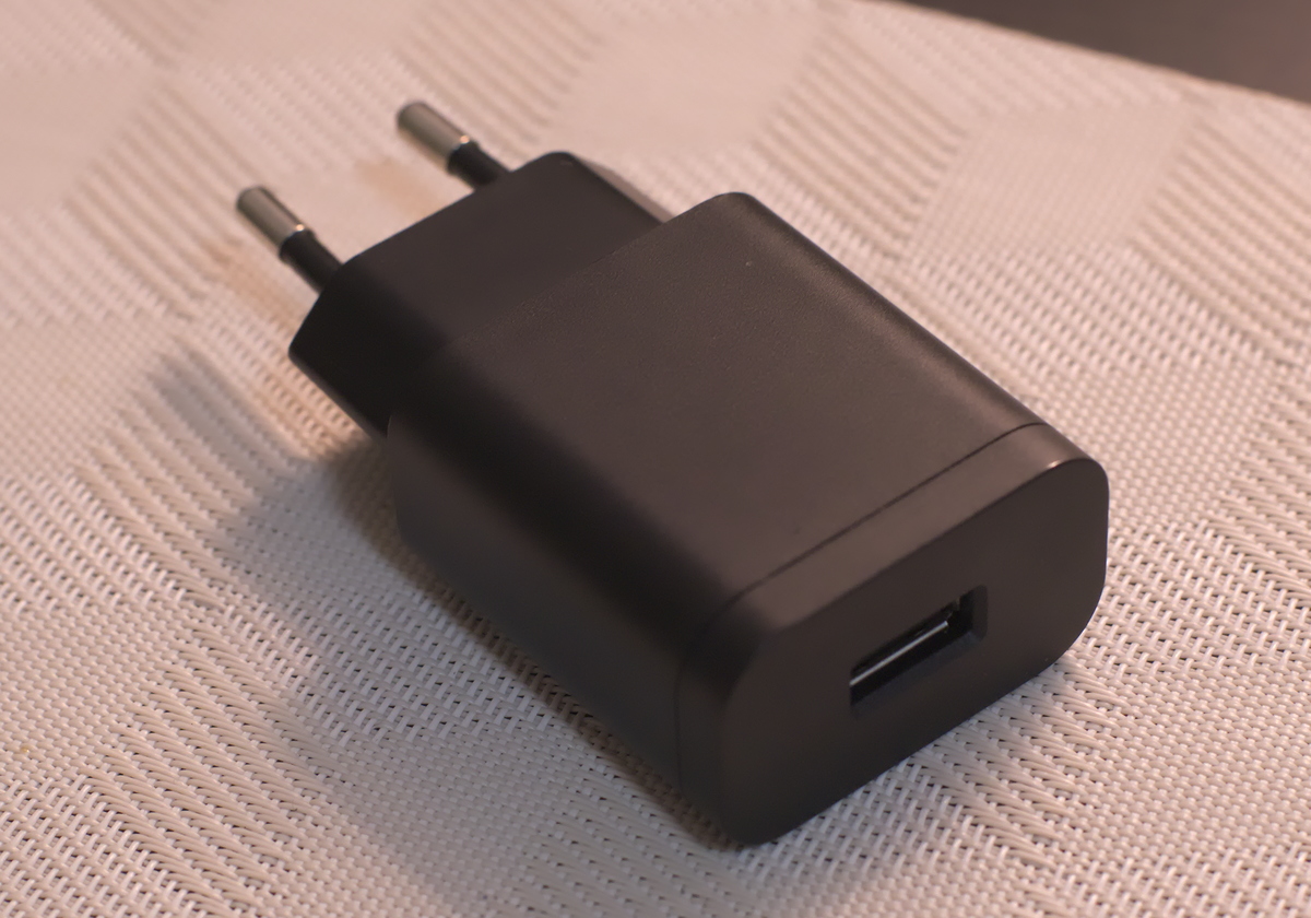
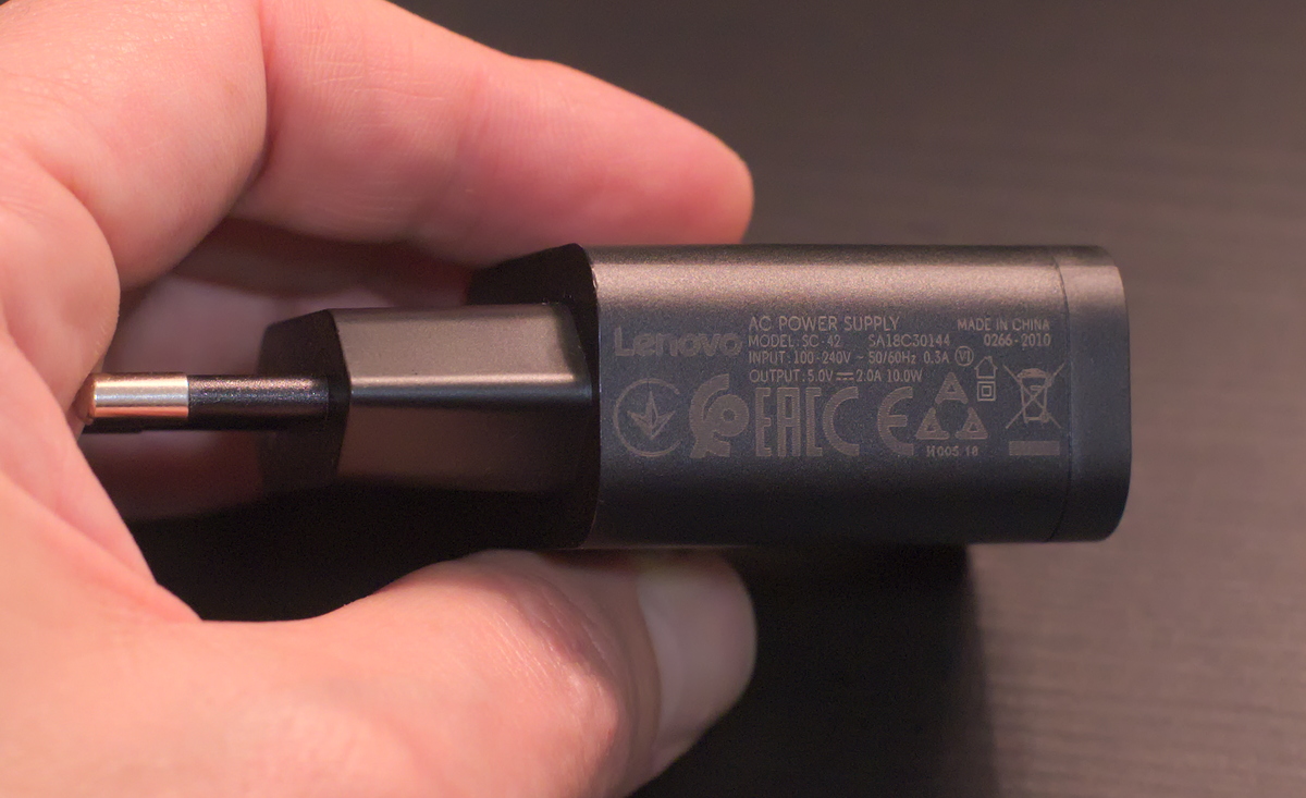
It's important to choose a high quality charger with a minimum of 1.5 amp current capability. There are a lot of bad USB chargers out there, please look around for a good one and load test it and check the ripple with an oscilloscope.
This unit performs okay and is made by Lenovo. It is rated for 2A:
Desoldering the 5V regulator PCB:
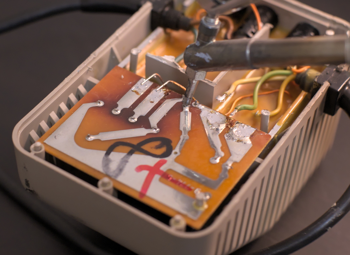
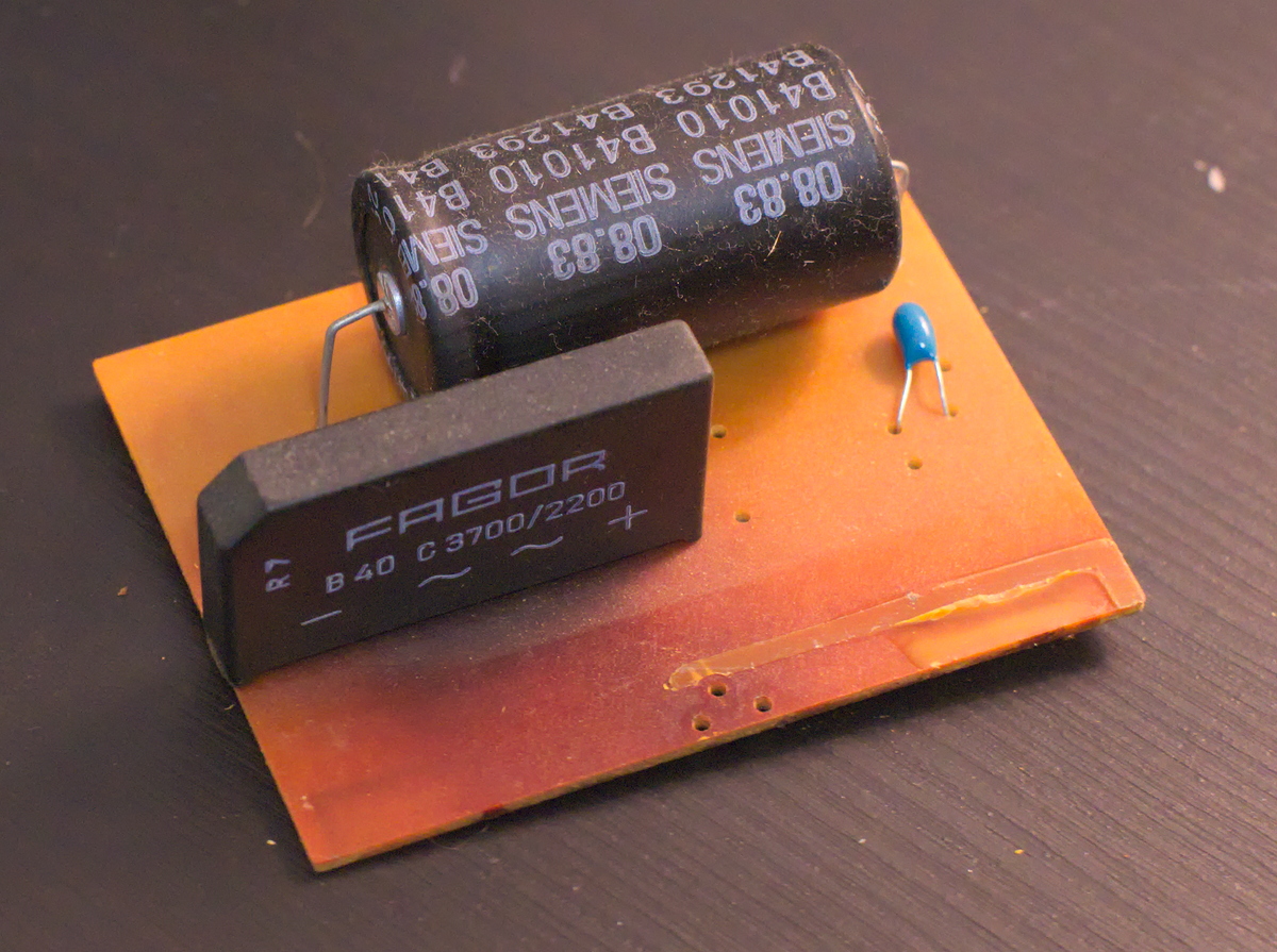
The board comes off. It shows sign of having been running very hot. The electrolytic is rated 4700uF 16V.
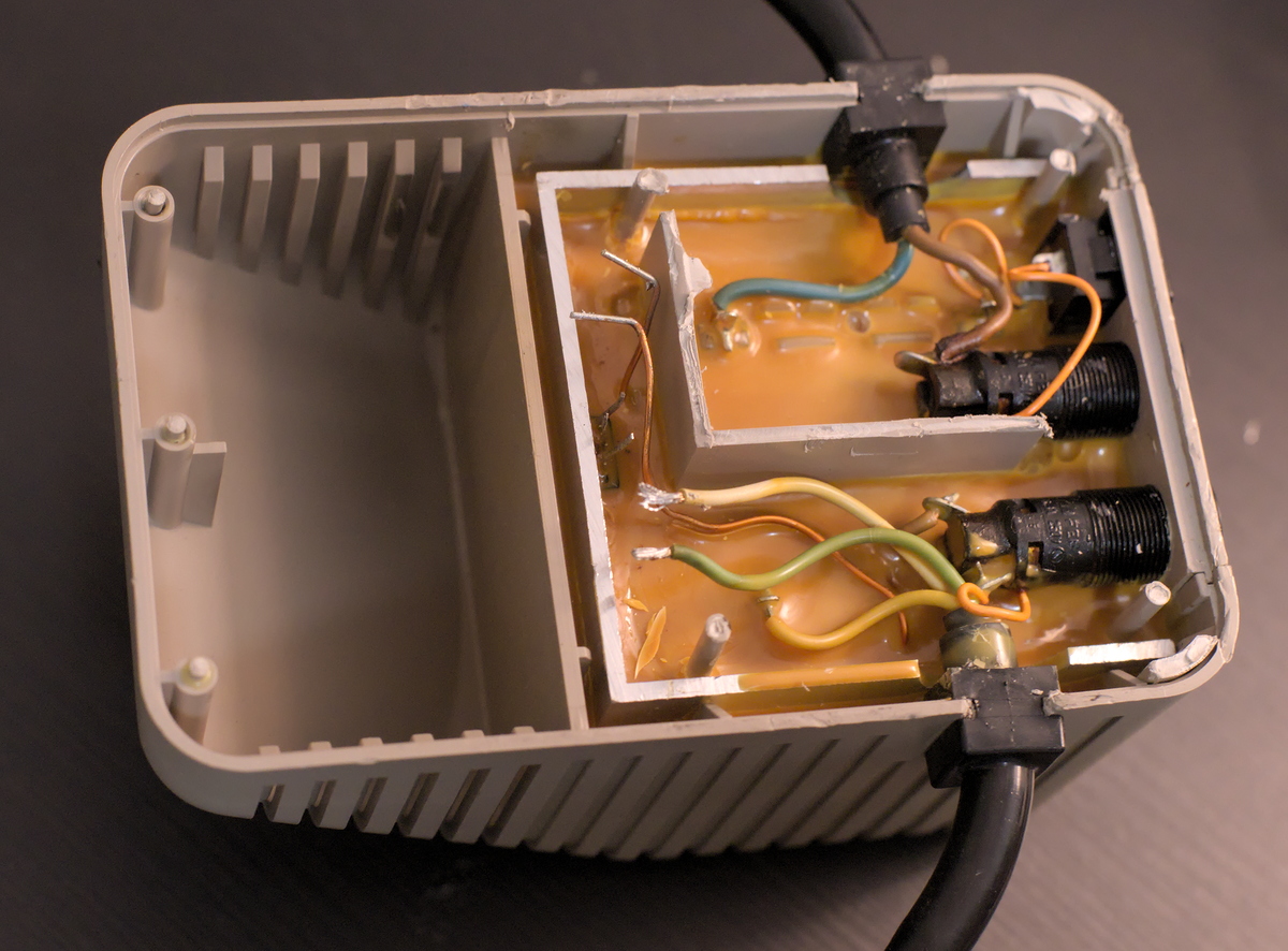
The PSU without the PCB:
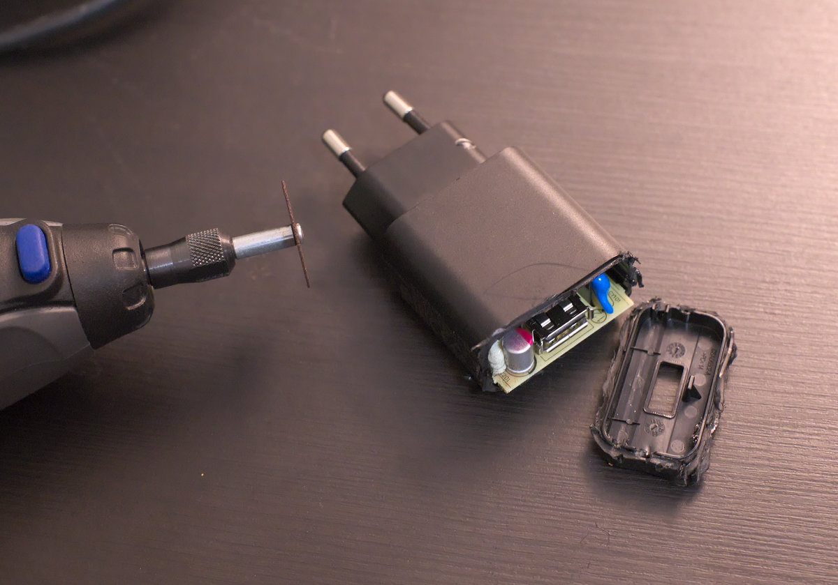
A dremel was used to get inside the donor USB charger:
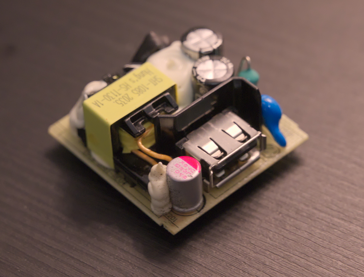
The PCB pulled out easily:
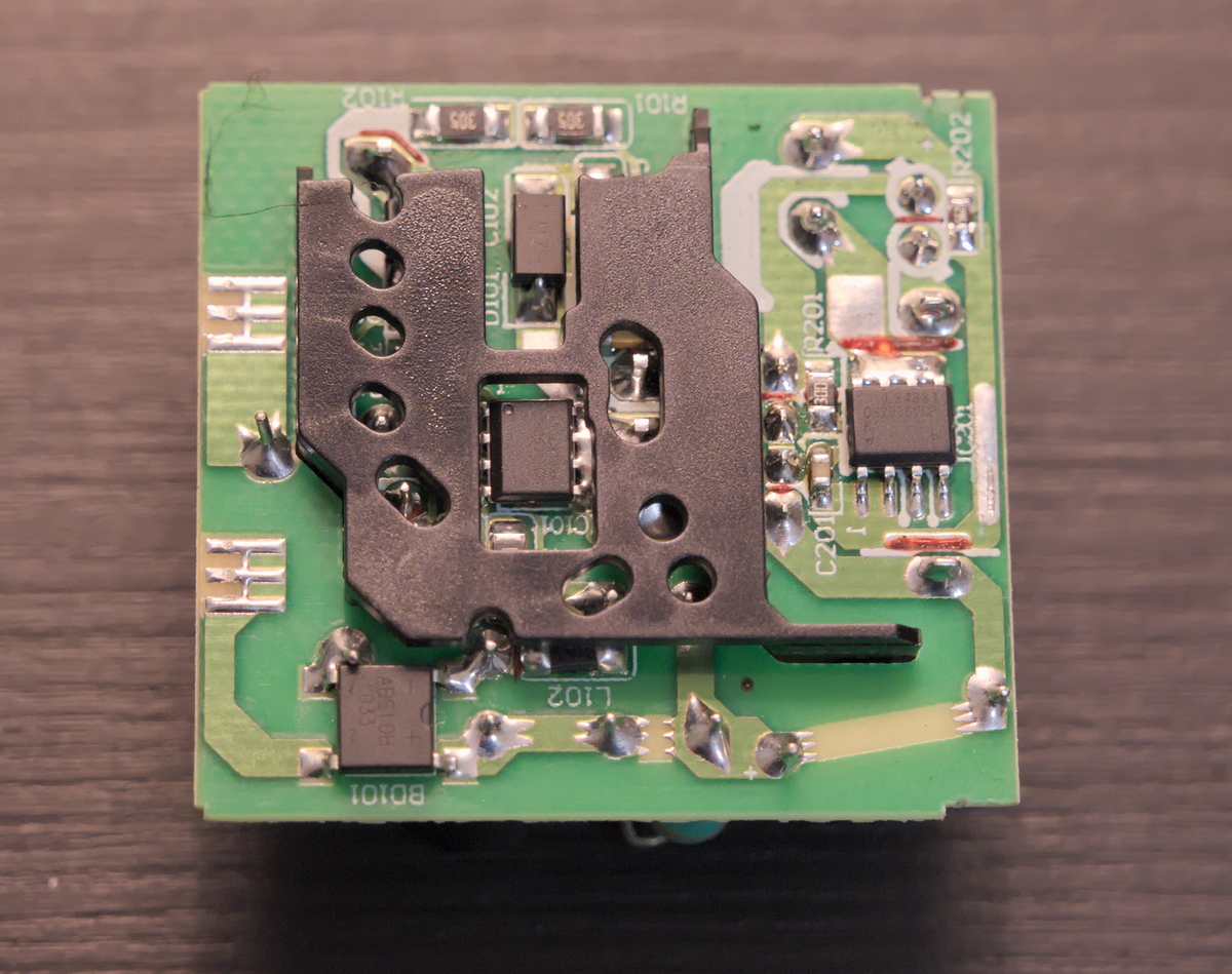
The mains voltage for the USB charger was taken after the fuse and ON/OFF switch. The unused transformer leads were terminated with heat shrink tubing:
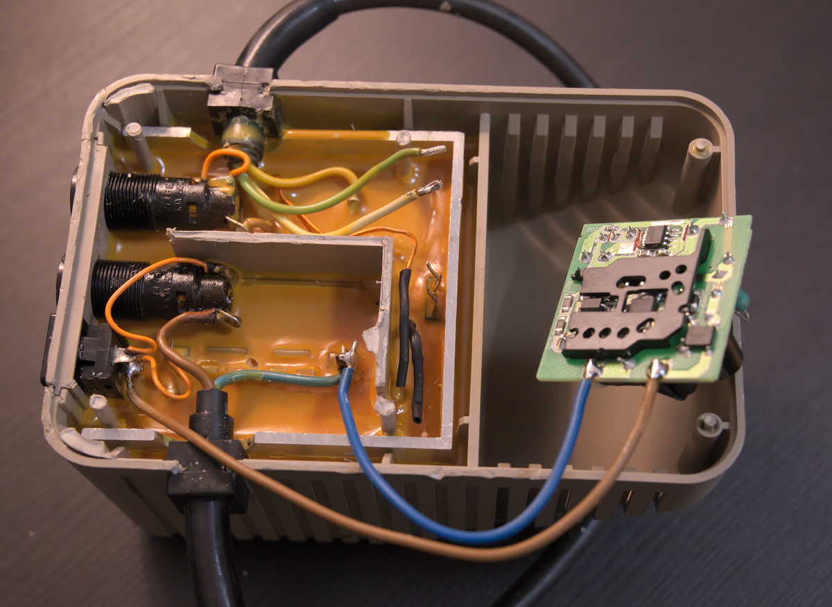
Connecting the 5V output. Be sure to get the polarity right!
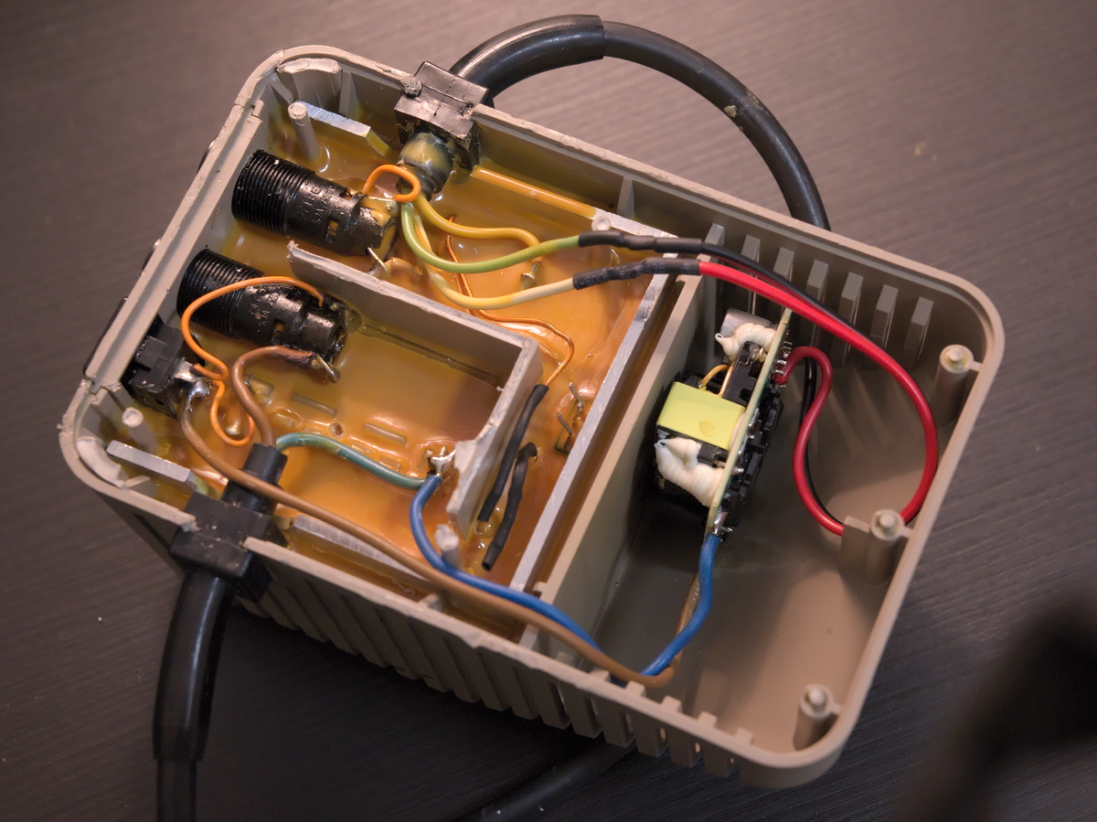
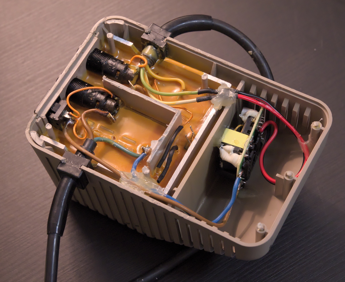
The wires and the PCB were secured with hot melt glue:
I took a look at the fuses and they turned out to be very crusty and needed a good clean:
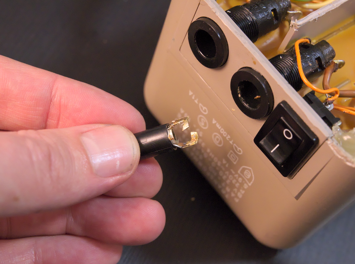
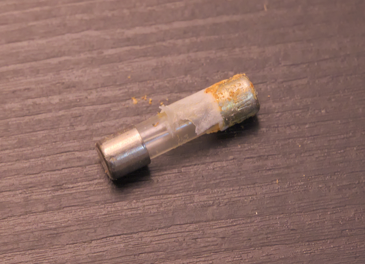
The unit was cleaned and put back together:
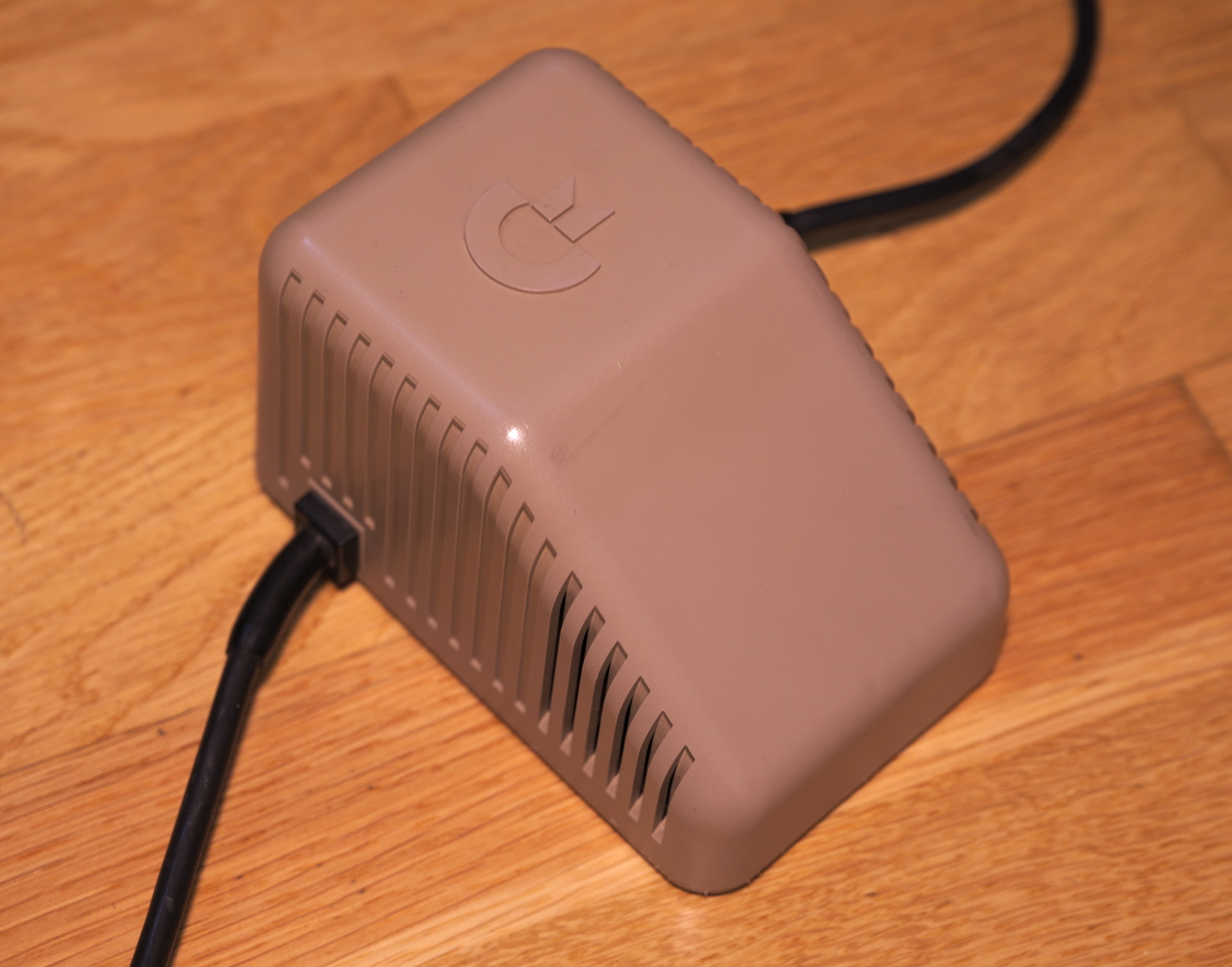
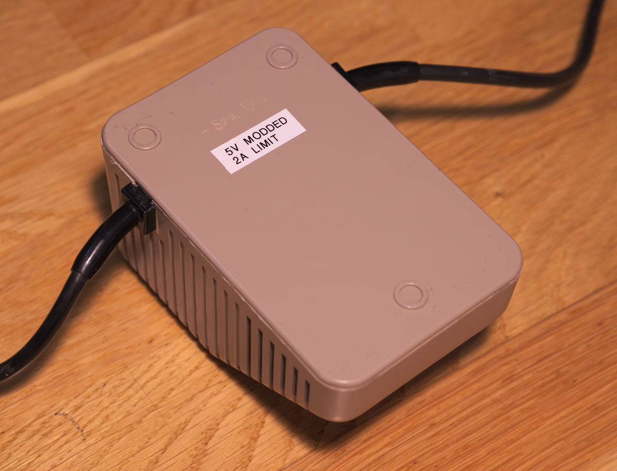
Before the modification, the unit would get quite hot after a while. Now it only gets slightly warm to the touch. I have had no stability issues of any kind with this modified power supply.
I hope you enjoyed this content!


Comments powered by Talkyard