The RetroCropper
An original Commodore 64 generates a white line artifact at the left of the picture. It's normally invisible due to screen cropping, but some upscalers don't crop the picture making the artifact clearly visible on modern TVs. The RetroCropper device presented here can process composite and S-video signals to remove the artifact and perform other cropping tasks.
The project is open hardware and open source. Hardware design files and software can be found on GitHub.
Table of contents:
- Introduction
- PAL VIC-II video output on an oscilloscope
- Technical description of RetroCropper rev. A
- RetroCropper Mk2 ideas
Introduction
Using an original Commodore 64 on a modern TV with good results requires proper upscaling of the video output. Most commonly available analog to HDMI upscalers are made for actual video and will try to de-interlace the image. This is not ideal for retro computers such as the C64, as it will introduce significant latency and artifacts. The RetroTink family of devices, on the other hand, are great for retro computers, but they don't, to my knowledge, perform much cropping of the image leading to the issue at hand for this project.
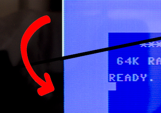
The following picture shows a PAL C64 breadbin S-Video output on a 4K TV, upscaled by a RetroTink 2x clone, clearly showing the white line artifact at the left. (I would love to get hold of a real RetroTink, but they are very hard to find in Europe. I'm not very happy with the clone as it doesn't seem to perform proper filtering of the PAL signal leading to horizontal bars and color artifacts.)
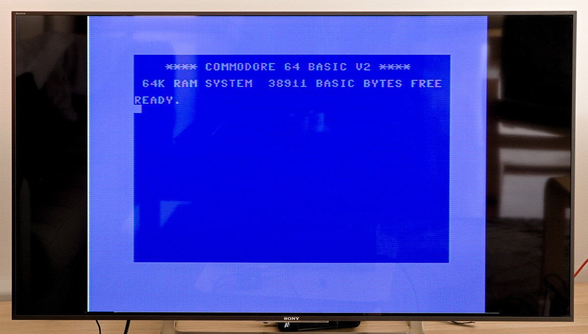
The white line is even more prominent when the screen border is black:
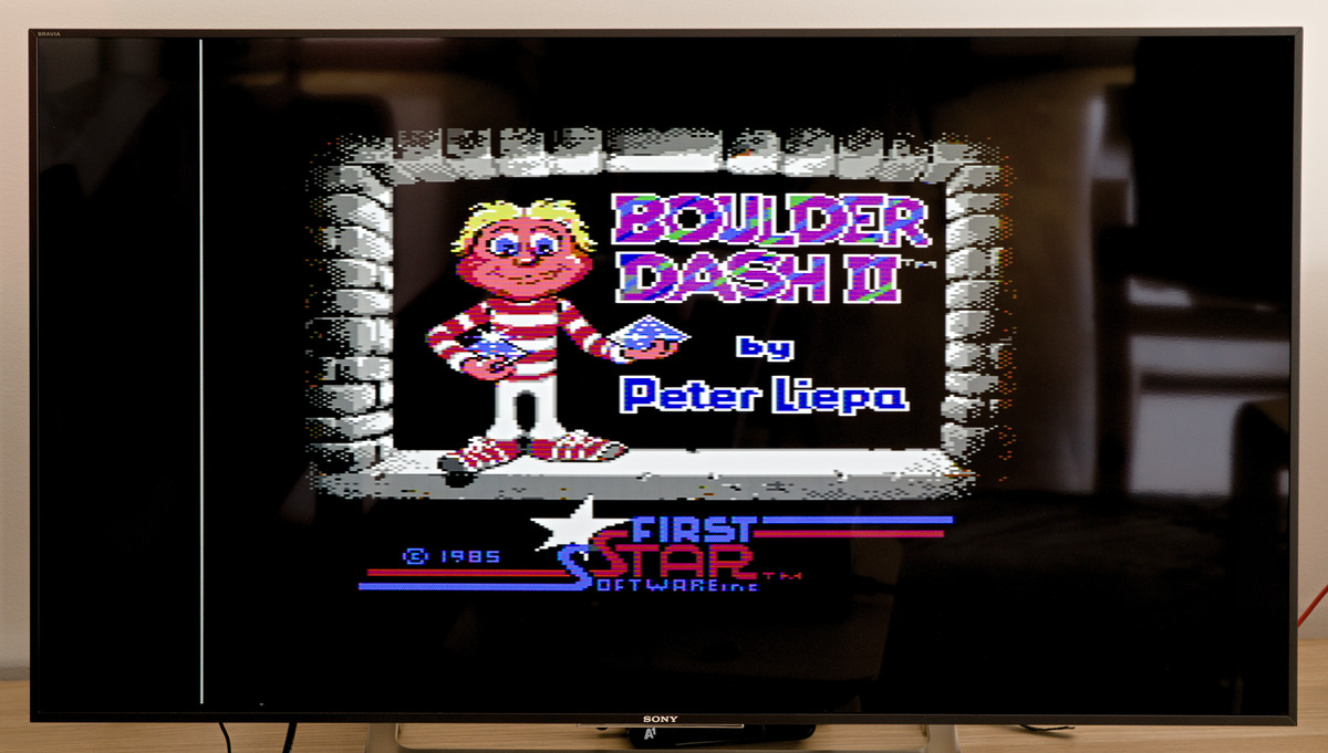
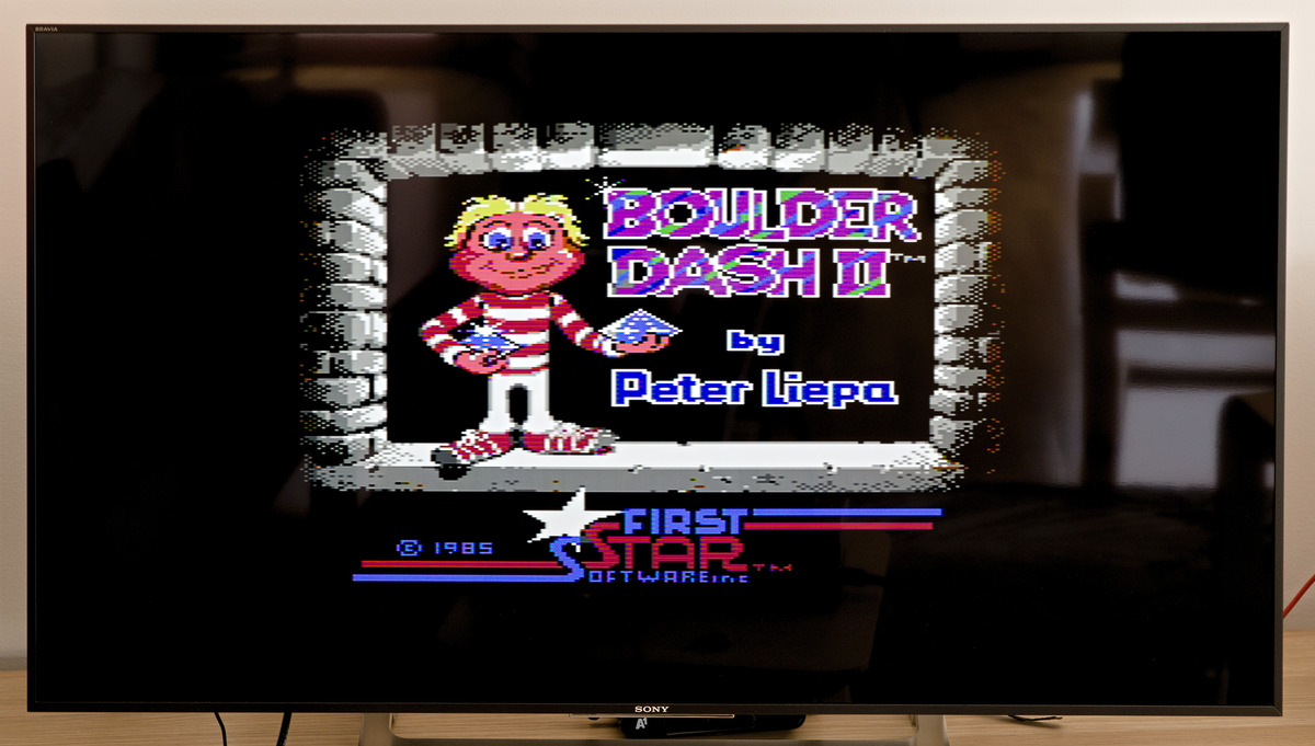
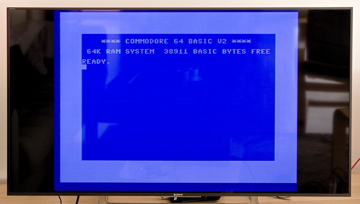
Activating RetroCropper removes the line:
RetroCropper has four modes of operation, pass through and three cropping modes:
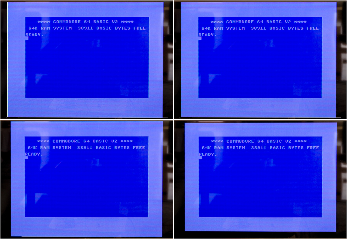
- Pass through (top left)
- Only cropping the line artifact (top right)
- Cropping the left border a bit more to be symmetrical with the right (lower left)
- Full cropping, that also removes a slice from top and bottom borders (lower right)
The modes are toggled by pushing a button. The mode selection is stored in non-volatile memory and restored after power-off / power-on.
Note that the device is experimental and not perfect. Sometimes jitter can be seen on the cropped edge due to the microcontroller operating with a 20 MHz / 50 ns resolution resulting in a +/- 25 ns accuracy of the timing of the cropping. To my surprise it turned out to be visible, although only sometimes and only when the screen border isn't black.
The next version of RetroCropper (if I'll make it) will be using a faster controller to eliminate this problem.
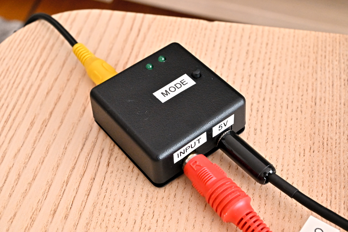
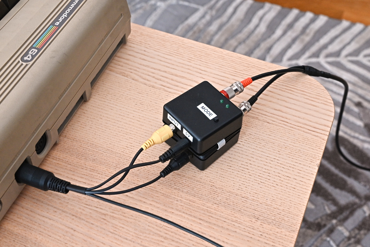
Here's the RetroCropper connected to crop a composite video signal:
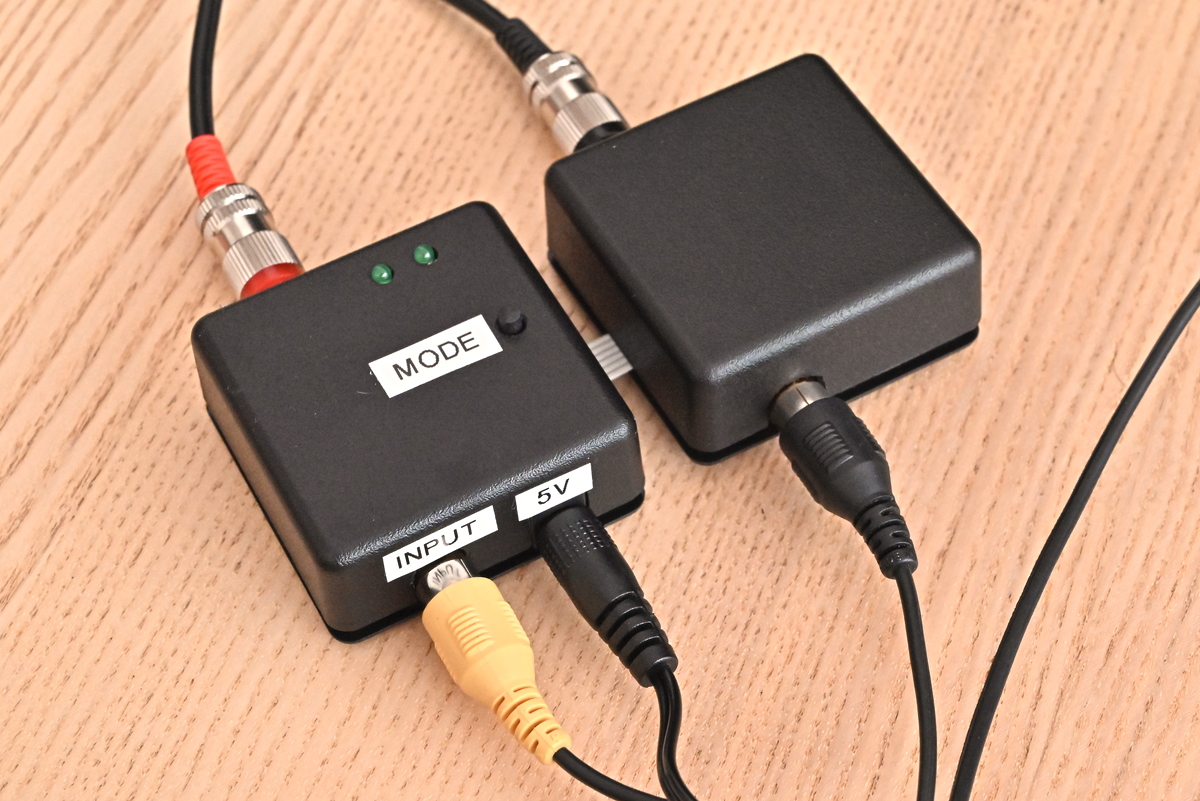
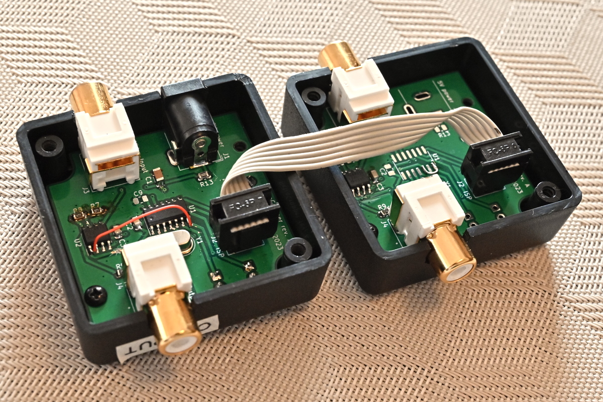
To crop S-Video it turns out to be necessary to crop both luminance and chrominance signals, I didn't realize this at first. Wiring up a second box can be done to take care of the chrominance signal:
As an aside, this is what happens if chrominance is not cropped along with luminance: (RetroCropper in full cropping mode)
I made specialized cabling that draws 5V from the C64 video jack and routes the S-Video components through RetroCropper:
PAL VIC-II video output on an oscilloscope
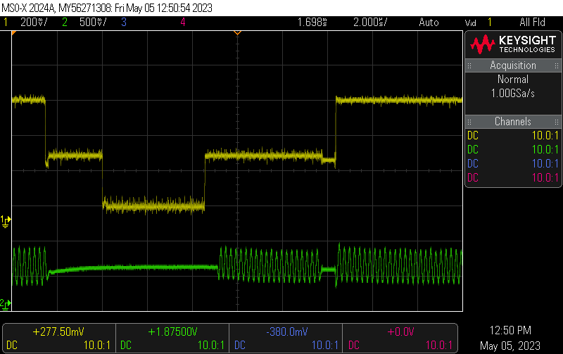
The white line is essentially a glitch in the C64 VIC-II output resulting in a brief, high, luminance level at the start of each scan line, shortly after the color burst.
Here is the start of a PAL C64 composite video scanline on an oscilloscope, showing the artifact. The low voltage interval is the horizontal blanking sync. After that comes the colorburst, the glitch and the blue border color.
Activating RetroCropper in the first mode removes the glitch:
S-Video
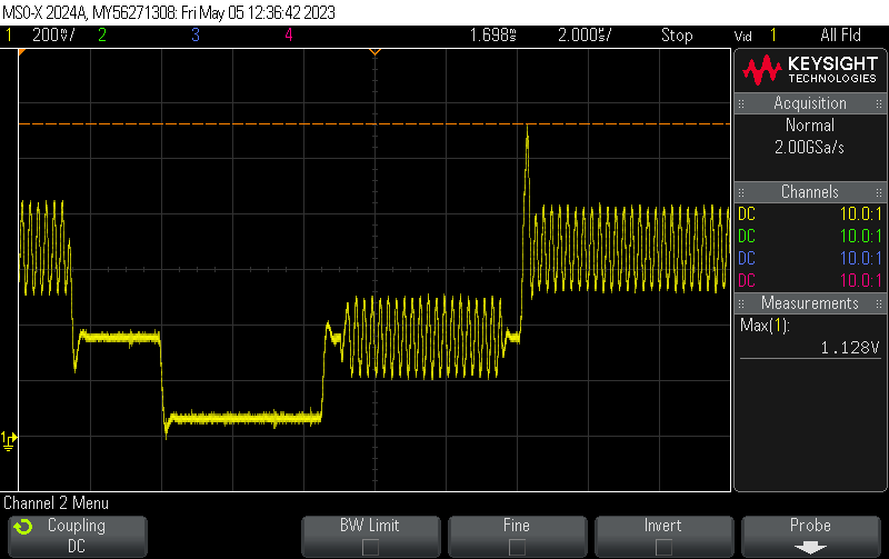
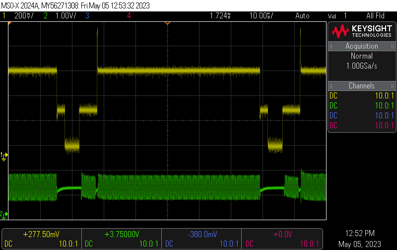
Here are the C64 chrominance and luminance signals directly out of the breadbin. Notice the chrominance trace is in 500 mV per division and according to many posts online, the voltage level is too high for the actual S-Video specification.
Feeding the signals through RetroCropper to remove the artifact. Notice the chrominance level is lower than before, which is intentional:
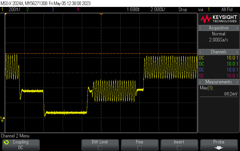
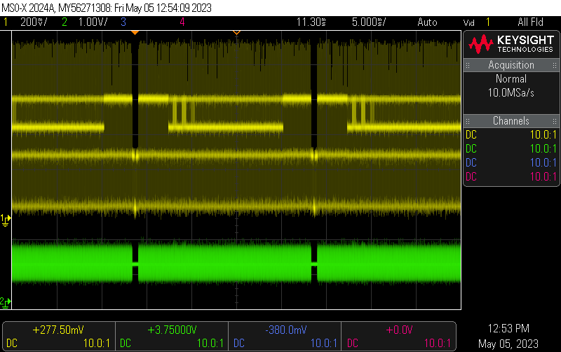
Here's a full S-Video scan directly from the C64 including glitches:
A couple of full S-Video fields. Notice the borders and the lines of text of the C64 start up screen can be seen.
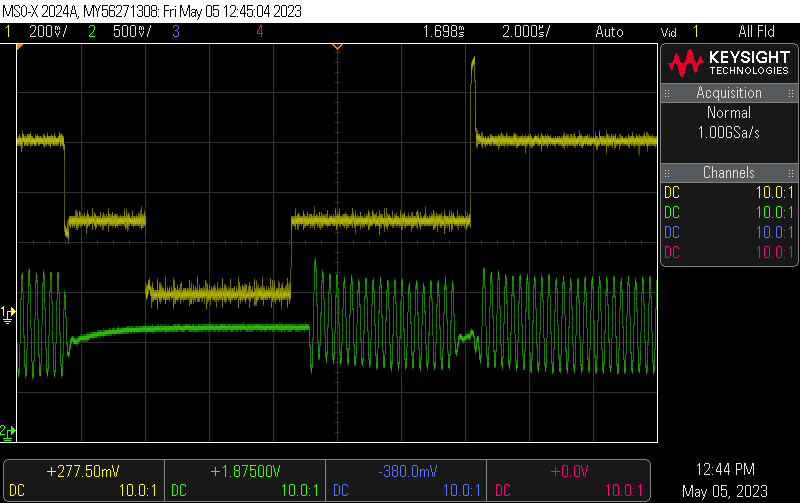
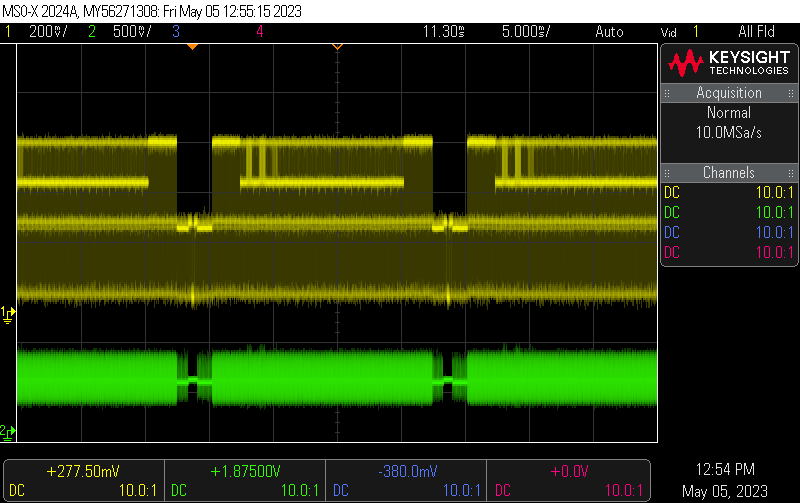
The S-Video fields through the RetroCropper in full cropping mode removing all the glitches and triming the borders:
The oscilloscope measurements were made connecting the probe over a 75 ohm resistor between signal and GND, to perform correct termination.
The C64 masured here is an unmodified PAL breadbin of a later revision featuring the 8 pin video DIN plug including 5V on a pin.
Technical description of RetroCropper rev. A
The approach is to have a microcontroller trigger on video sync pulses and with careful timing switch between the video signal and a constant black level at certain times during the scanline. In rev. A this is done with a Atmel ATtiny841 microcontroller and a Maxim MAX4310 video switch.
The schematic, with an errata:
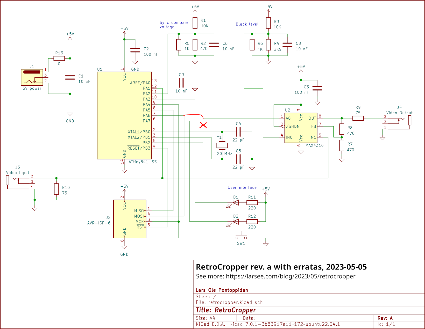
The sync compare voltage divider creates a voltage for the ATtIny analog comparator to compare with the video signal for capturing sync pulse transitions.
Another voltage divider creates the black level voltage used when blacking out the video signal.
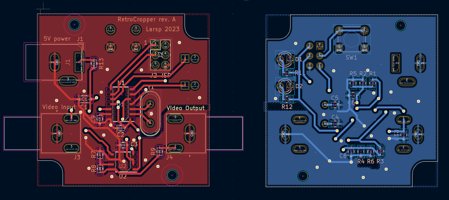
The PCB design:
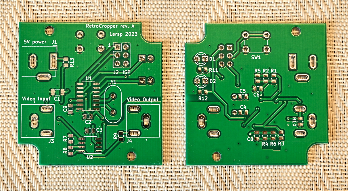
The bare PCBs were ordered online and came out allright:
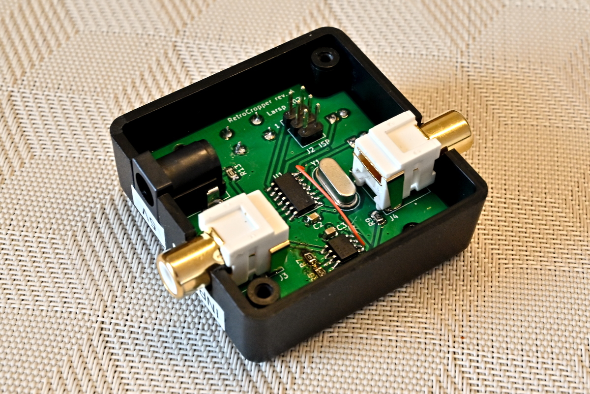
Fully mounted in a box:
Adding a secondary unit to filter chrominance:
Issues with rev. A:
- The video switch signal was mistakenly connected to PB2 with the OC0A function (timer 0 output compare). It has to be connected to PA6 instead, with OC1A (16-bit timer 1 output compare) in order to achieve optimal timing accuracy.
- As mentioned, even full 20 MHz / 50 ns resolution, the fastest possible with this family of microcontrollers, is not fast enough to perfectly time the edges of cropping.
- Some components are physically too high for the chosen box: Hammond 1551R
- The footprint for the RCA receptacle is not correct. The legs has to be bend a little.
- The design is only for cropping one channel, which is fine for composite. For S-Video both luminance and chrominance must be processed requiring two PCBs.
- The software only supports PAL at the moment. NTSC support should be possible but requires other timing parameters. I'm unable to implement this as I don't have access to an NTSC C64.
How to make a secondary PCB to process chrominance:
-
The second PCB should be only partially populated, and with some different component values:
- Same as main schematic: C1, C3, C8, MAX4310, R3, R9, R10, J2, J3, J4
- Different values: R4: 5K6, R6: 4K7, R7: do-not-mount, R8: 0R
-
A 6-pin ribbon cable can be used between the ISP connectors to transfer GND, 5V and the video switch signal
- A bridge must be made from pin 5 to 7 on the ATtiny footprint, such that the video switch signal makes it to the MAX4310
- Note that the MAX4310 is configured for unity gain here instead of x2, cutting the chrominance output level in half (due to 75 ohm terminations). This is intended and brings down the too hot C64 chrominance signal to a more acceptable level.
RetroCropper rev. A hardware design and software can be found on GitHub.
RetroCropper Mk2 ideas:
The ST Microelectronics STM32G series controllers, like the STM32G431, might be able to perform the entire cropping task perfectly without needing almost any external components. It runs at up to 170 MHz, has DA converters to generate both the threshold voltage and black level, and features built-in configurable op-amps that may be suitable for handling video signals.
The video cropping might be combined with an audio amplifier to protect the SID chip, making a single device that does all the signal conditioning one might want for the C64 A/V output. This device might be integrated with a cable for a neat solution. Note that this would only work with later breadbins or C64Cs that feature an 8 pin video connector with 5V available on a pin.
Please let me know if you might be interested in such a product!
I hope you enjoyed this content!

Comments powered by Talkyard