SickSack
This is an unedited republication of the SickSack project description as it appeared on the first Lars' Electric Endeavors website. SickSack is a line following snake robot that uses only slithering mothing to move.
Lars, January 2018
This article is about the robot: SickSack that Aske Olsson and I created for DTU RoboCup 2007, which is an annual competition for autonomous mobile robots held by Automation at the Technical University of Denmark.
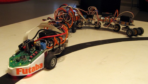
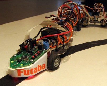
The robot consists of nine cars connected with eight Futaba servos controlled by a microcontroller. All wheels are passive, the locomotion comes entirely from lateral undulation, which is wave movements in the plane similar to a snake.
Continue reading for the story behind the project, how we fared at the RoboCup competition with videos, and for details about the electronic hardware, mechanical construction and software.
The Story
In DTU RoboCup, mobile robots have to score points by driving through an obstacle course and completing certain tasks of various difficulty. As the robots must be autonomous, they can't be controlled by humans or by other external means, they must complete the track on their own. A black tape line on the floor defines the basic course.
Aske Olsson and I always wanted to participate in the competition with a home built robot. But what should the robot be like? Definitely, the most sane design decision would be to have regular wheels and rotate them with motors for locomotion, and then add a bunch of sensors to the platform. This is indeed the approach that nearly all other competitors use. So if we were to get some attention, we had to either create a superb conventional mobile robot that could compete with the others, or come up with something radically different. We selected what seemed to be least painfull at the time.
One day the idea emerged: why not move about as a snake does? That would indeed be radical, even cool, and we wouldn't have to mess with powered wheels and the steering could be implicit in the snake motion. As time went by we developed the idea, brought components and designed and ordered the controller board. An important milestone was when we got Futaba RC to sponsor us with servos. The servos would otherwise have been the most expensive items on the budget.
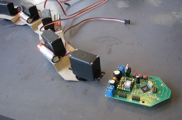 Early cardboard prototype and controller board
The RoboCup Qualification
As we got nearer the day of the RoboCup competition, we managed to get under considerable time pressure. We had to do the construction, assembly and programming in less than a week. But thanks to coffee, rotary debuggers and high motivation we probably had our most productive couple of days there.
The evening before the RoboCup qualification we had just gotten the thing assembled and wired, which meant that tenths of kilobytes of mostly untested code had to be ironed out. That was extremely stressing, because we had to perform the next day, and the entire AVR microcontroller programming with 8 channel PWM generation, timers, interrupts, AD conversion, fix point math, motion control etc, all just had to click.
The morning before qualification the entire system was up and going, except that the algorithm for following the black tape line was still not working properly. The robot would frequently loose the line, and facing time pressure, we had to give up following the line. But we really needed to score one single point to qualify, which meant getting the robot to pass through a guillotine gate within a time limit. So we went for straight snake motion and the aiming principle. Thanks to a good share of luck, we pulled it off, in the second try.
 SickSack at DTU RoboCup 2007
The RoboCup Competition
Having passed the qualification was a big relieve and gave us one more day of work before the final competition. That extra day was mostly spend improving the software, but it was surprisingly difficult to get the line following algorithm up and going in a stable manner. The following video shows a test of an early not-yet-perfect version, where the robot just about fails passing through the guillotine gate in time:
After further improvements, we got the line following fixed and working pretty well. We were ready for the competition! The following video is of the first competition round:
First round went pretty much as expected, although the robot fell off the ramp to the right, which was not intended. Second round had a more interesting end:
RoboCup Result
Well, SickSack got three points, which was enough for 13'th position out of 15 participants. But we got the Best Design and Effects award which we appreciate a lot!
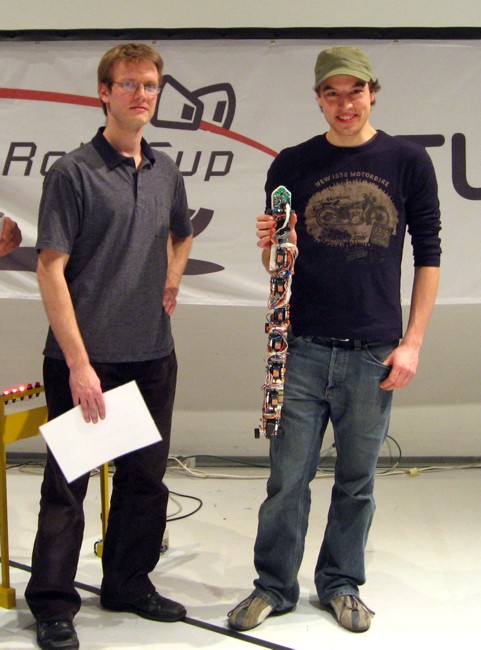 Lars Ole Pontoppidan and Aske Olsson after receiving the Best Design and Effects award at DTU RoboCup April 12th, 2007
The SickSack Controller
The active parts of the SickSack robot are eight standard size RC servos:
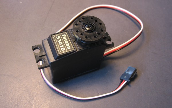
Futaba RC sponsored our project with ten of these S3010 servos which feature ball bearings and high torque and speed. This project would not have been possible without this support.
The servos need a power supply of 5 to 6 volts with adequate current capabilities and a PWM control signal. A controller board and battery system had to be designed for supplying this.
Power Supply
The power supply problem was solved by taking advantage of a Texas Instruments Turbo Trans power module: PTH08T220W and having eight AA size NiMH cells in series. The power module is a very compact DC to DC buck converter able to step the down from 14 V to 5.5 V delivering an incredible 16 amperes.
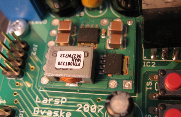
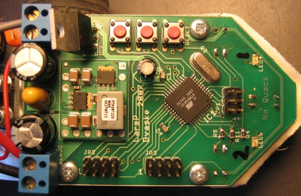
The Texas Instruments PTH08T220W power module embedded on the controller board.
In the photo, to the right of the power module, an 7805 can be seen, which powers the microcontroller and other stuff. We felt it was a good idea to isolate the digital power supply from the servo power supply.
The battery system had to be capable of delivering a couple of amperes, and we discovered that battery containers often adds considerable ohmic resistance. That was unacceptable, so the solution was to get cells with solder tags, and simply solder all battery connections. A breaker switch and a connector for charging the batteries were mounted.
The Controller
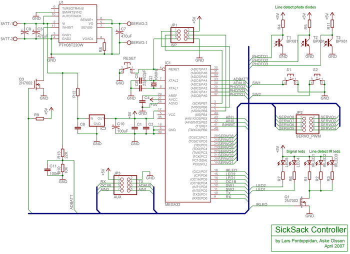
A single Atmega32 microcontroller was utilized for all control tasks. We had already verified that it was possible to generate eight servo PWM signals without taxing the MCU very much, so we thought that a single controller should be able to do the job.
For sensing the black tape line on the floor, three photo transistors and illumination with red LEDs were employed. By measuring the light level with illumination on and off alternatingly, the reflectivity of the floor could be estimated. The photo transistors provided plenty of amplification in themselves, and no other gain stage was required before the AD converter. Actually saturation was a problem with the high level of infrared energy in the lightning on the RoboCup track.
The user interface was simply two buttons and two signal leds. Have a look at the complete schematic:
The controller board layout, as routed from the schematic:
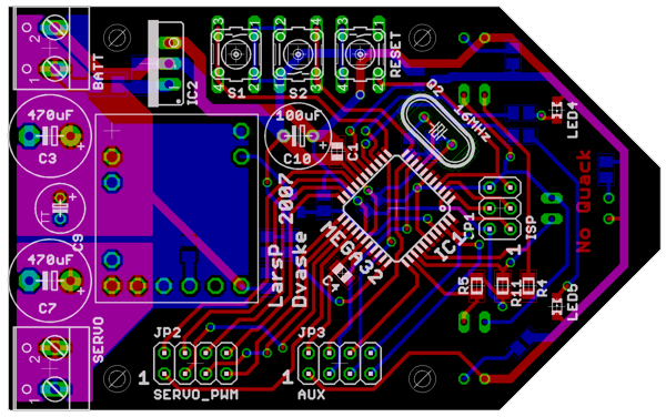
The PCB was ordered at Olimex, and the result was quite satisfactory as always. The completed SickSack controller:
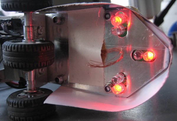
From below, the LED illumination and photo transistors can be seen. The copper whiskers were installed to eliminate ESD problems.
Construction of SickSack
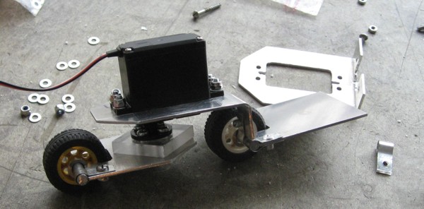
The mechanical concept of SickSack had been roughly outlined in the cardboard prototype:
Aluminum adventures
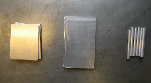
We just began creating an aluminum version of that prototype and dealt with the problems and design decisions along the way. The raw construction materials were 1.5 mm aluminum plate and 5 mm aluminum rod axes:
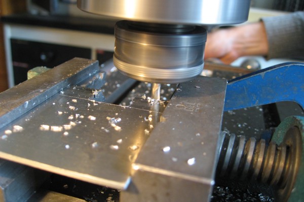
A milling machine was used extensively to craft the servo mounting holes and the wheel slots:
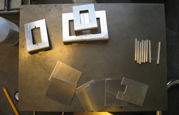
Slowly, but steadily, the aluminum plates began to take shape:
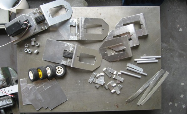
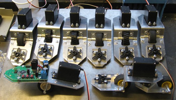
LEGO wheels were used, and the hinges were manually crafted from iron plate and riveted in place:
There had to be a 6 mm offset from the servo horn to the next car. This was accomplished with plexiglas:
Quite some time later, the cars were completed and the snake head and tail designs were decided:
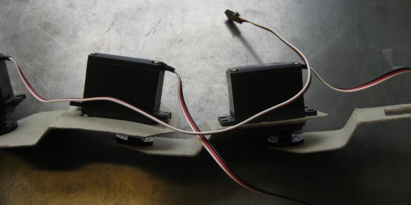
Wiring
Connecting and mounting everything was much more time consuming than we had expected.
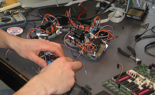
The initial design, with single wheels under the cars, turned out to be inadequate as the snake tipped over all the time. This was solved by prolonging the first, center and last wheel axes to have three wheels.
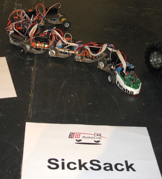
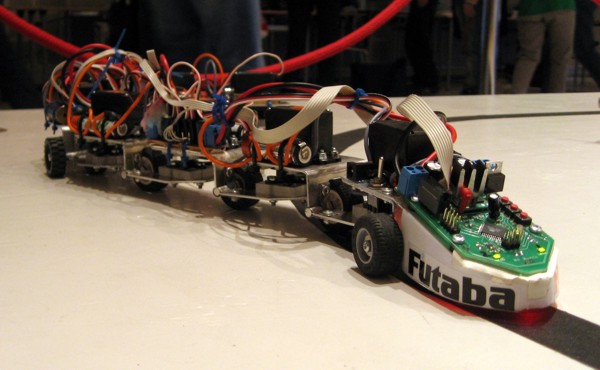
It was necessary to add a skirt at the head to block the high intensity RoboCup scene lightning from saturating the photo transistors. Thus the completed SickSack robot ended up looking like this:
SickSack Software
The SickSack controller interfaces all components and creates and controls the slithering movement. In summary, the microcontroller had to be programmed to perform the following tasks:
- Generation of eight servo PWM signals, in a 50 Hz cycle.
- AD conversion of three photo transistor voltages with floor illumination on and off.
- Calculation of the slithering motion sine wave and its propagation along the snake body.
- Controlling the motion such that a line could be followed.
Servo PWM Generation
The servos in themselves work as position servos, actively trying to hold a position (angle) that is commanded by the signal pulse width. This PWM signal consists of pulses with lengths from 500 to 2100 micro seconds, repeating at 50 Hz.
The 20000 micro seconds in a 50 Hz time frame conveniently allows for creating the eight servo pwm pulses one at a time. This meant that an implementation entirely based on timer interrupts was possible, such that the pulse widths were defined by the timer output compare register.
AD Conversion
The 50 Hz time frame, as required by the servos, was adapted for the fundamental control cycle time frame. This meant that a new differential sample from each photo transistor should preferable be available 50 times a second.
Thanks to the AD conversion capabilities of the AVR, that was easily achieveable. In fact, the implemented AD conversion scheduling provided four samples for each photo transistor for both illumination on and off for each time frame.
The Slithering Motion
The basic concept of the snake motion is that the angle of the head servo does in turn become the angle of the second servo, the third servo, fourth servo etc. and finally the tail servo, corresponding to the progress of the robot movement.
This basic principle leads to an implementation where the head servo angle solely defines the motion, and a buffer stores the history of head angles for the rest of the servo angles. The implemented circular buffer have 16 slots between each servo, such that 16 steps in the buffer would result in having a given servo angle appearing at the next servo. The speed of stepping forward in the buffer thus defines the speed of intended snake movement.
To define the snake motion thus meant to command the head servo and to decide how fast the buffer should step forward. A sine wave was generated for the head servo motion, with possibilities for defining amplitude and frequency. The sine implementation relies on a lookup table.
Line Following
SickSack only sees the line on the floor when the head moves over it. Implementing a line following algorithm based on this sensor information was somewhat difficult.
The final algorithm had to work on two levels. Basically the robot constantly keeps track of whether the line is at its left or right. When the line is at the left, the head angle wave is added an offset resulting in the robot turning slowly to the left. When the line is at the right, a similar offset of opposite sign is added to make the robot slowly turning to the right. This seeking motion can be observed when the robot is away from the line.
That principle alone, however, does not lead to a very stable line following performance. Another level of feedback is also performed in the algorithm, the phase of the head wave. Whenever the head crosses the line, the phase of the sine wave is forced to either 0 or Pi radians. This means that the oscillation sort of locks on to the line on the floor. The feedback concept was not easy to get going, and had to be improved with a number of additional rules. But the result was a stable and good performing line following algorithm.
Where's the source?
The source is not downloadable, as it is in a rather rough state and possibly contains a lot of bugs. It shows that large part of the code was conjured in a few days of stressful hacking.
Afterword
First of all we would like to thank Futaba RC for sponsoring our project with the S3010 servos, which were a joy to work with and proved to be very reliable and high quality servos. We must also thank Texas Instruments for their generous product sampling policy and in particular that we could get the excellent PTH08T220W power module.
Thanks must also go to Institute of Automation at the Technical University of Denmark, for being generous with tools, space and time for our hobby projects, and of course for holding the DTU RoboCup competition.
Spaceman Spiff, Anders Beck and Lars V. Mogensen also deserves special thanks for assistance and good company during the project.
We'll be back next year!
Lars Ole Pontoppidan and Aske Olsson
April 2007
I hope you enjoyed this content!

Comments powered by Talkyard