The Wooden DTV
This is an unedited republication of the Wooden DTV project description as it appeared on the first Lars' Electric Endeavors website. The DTV is a C64 in a joystick product released in late 2005. Enjoy!
Lars, January 2018
This project was inspired by the countless other projects on the web concerning hacking and modifying the C64 DTV. The basic goal I had with my DTV modding was to create a handy little C64 clone you could bring along to spread some 8-bit joy.
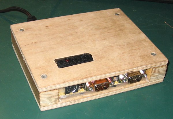
Although the Commodore 64 was a handy unit compared to other contemporary computers, you would want to have a very good reason to bring along your breadbox, 1541 drive and a box full of disks. My Wooden DTV changes all that. Within the modest measures of 14 x 11.5 x 3.2 cm it can embody gigabytes of 8-bit old-schoolness: Wooden c64 dtv case mod Features
The Wooden DTV is basically a PAL DTV (DTV ver.2 batch: 05 10 08) built into a wooden case with connections for Joystick 1, Joystick 2 and PS/2 keyboard. Power supply circuitry has been added such that a wall adapter feeds the unit. Also in the box is the MMC2IEC device I created to enable saving and loading from SD/MMC cards by simulating a 1541 drive. Read about that project here: MMC2IEC Device.
Continue reading here to learn how I did:
- The Case Mod
- DTV PAL circuit fix
References
This project has only been possible thanks to the excellent work done by other people. This is a couple of usefull links:
- C64 DTV Hacking Wiki
- Wikipedia about C64 Direct-to-TV
- Daniel Kahlin about C64 DTV
- Commodore DTV Hacking by David Murray
- Powerglitch about DTV modding
- Richard Lagendijk about DTV hacking
- Petscii DTV hacking forum
- Spaceman Spiff, who is a friend of mine, about DTV Hacking
The Case Mod
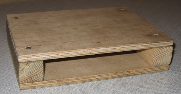
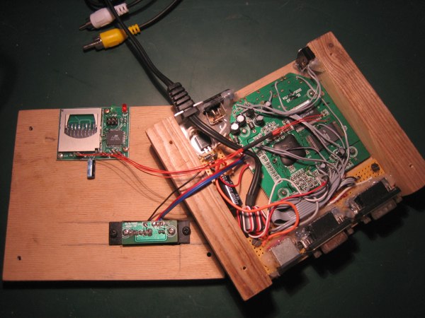
So, I wanted to build the DTV mainboard into something else not looking like a joystick, enabling you to connect your own joysticks and a PS/2 keyboard. One of my definite goals was to get a compact and handy unit, so this ruled out a lot of possibilities. Lacking other options, I decided to make the case myself. Since wood is a nice material, well, I chose to make a wooden case: Bare wooden case
So, I wanted to build the DTV mainboard into something else not looking like a joystick, enabling you to connect your own joysticks and a PS/2 keyboard. One of my definite goals was to get a compact and handy unit, so this ruled out a lot of possibilities. Lacking other options, I decided to make the case myself. Since wood is a nice material, well, I chose to make a wooden case:
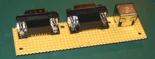
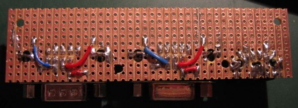
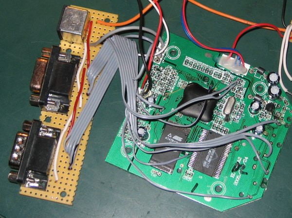
The DB-9 connectors for joysticks and the mini-din for keyboard were mounted on stripboard, with the use of some drilling and tweaking:
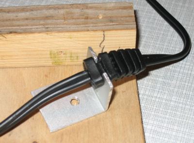
I decided to keep the AV cable instead of adding seperate connectors for audio and video. The cable needs to be secured somehow which I accomplished with this piece of aluminum:
Powersupply
The original DTV was powered by four AA batteries linearly regulated to about 3.3 V required by the ASIC. For this endeavor a 5 V line was also required to power the PS/2 keyboard, so I decided to make a 5 V supply and let the DTV regulate that to 3.3 V.
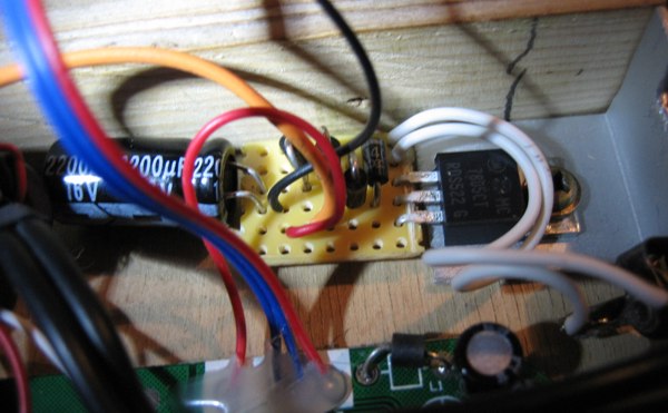
I found a suitable wall AC adapter and did a conventional full bridge rectified, capacitor smoothed, 7805 regulated power supply. The capacitor value depends on current demands and the accepted ripple before the regulator, and was empirically dimensioned to 2200 uF which is on the safe side. The alu piece just mentioned neatly doubled as a heatsink for the regulator:
Assembly
One of the mandatory challenges when doing a DTV mod, is to connect wires to the signals on the DTV board. Some signals are quite easy to connect because they have accessible copper pads, but others are to be accessed at vias on the PCB. This means you have to scratch away soldermask and solder the wire to quite a small spot. It is certainly possible, but you will need a steady hand and some thin solder wire comes in handy
Following the instructions at powerglitch.com I managed to connect my breakout board:
Everything almost worked from scratch, except that I had exchanged left and right direction on both joysticks...
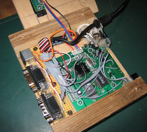
The boards were screwed into my wooden case and the original plastic piece with the ON/OFF button and power led was kept and mounted on the top plate.
It showed necessary to hot melt glue the connector PCB thoroughly to give mechanical stability. I will not recommend using stripboard for PCB mounted connectors in the future, it is too flimsy. But it is OK after a load of hot melt glue.
When I had finished the MMC2IEC device PCB, I mounted it on the top plate such that it is accessible from the back of the unit:
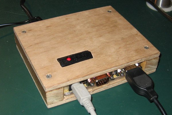
The finished Wooden DTV
Connecting a keyboard and a joystick to the completed unit looks like this:
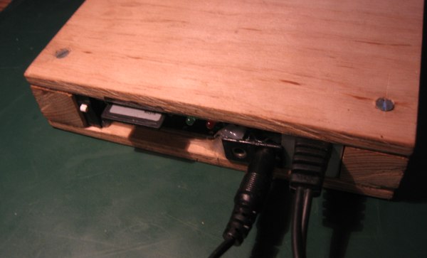
Looking at the rear, there is a reset button at the left. Next comes the SD card for the MMC2IEC device. And don't look too much at that power connector, its just a really old scavanged part.
Fixing the DTV PAL circuit
Out of the box, the PAL DTV creates horrible colors. This is not because of price cuts or design intensions, but because of mistakes on the PCB.
A short PAL primer
A composite PAL video signal consists of luminance and chrominance information, as well as sync and calibration signals, all packed into a single signal.
The luminance is the level of brightness and the chrominance defines the color saturation and hue. Basically, the way PAL encodes this is to have luminance as the voltage level added a 4.43 MHz sinewave, whoose amplitude is color saturation and phase offset is color hue. Thus the color information is stored in the highest frequency components of the signal while lower frequency information is used for luminance.
This is clever because a poor transmission of a TV signal with low bandwith will sacrifice color information before the brightness information, which the eye is most sensitive to. Also, old black and white TVs just ignores the color information and renders the luminance signal alone without problems.
DTV PAL generation
In order to generate such a signal the C64 DTV uses two R-2R resistor ladder DA converters, one for luminance and one for chrominance. With such a resistor ladder, you achieve voltage dividers of values 1/2, 1/4, 1/8 etc. for each digital bit such that DA conversion is a matter of applying the digital signals to the network and you have the analog voltage.
But. The R-2R ladders have wrong values of the resistors in the PAL DTV. They are basically swapped such that R is 2R and 2R is R, and one resistor is omitted completely. This completely ruins the linearity of the DA conversion and makes even the 16 colors of the C64 very inaccurate.
The FIX
Daniel Kahlin has a page about this problem, where you can see schematics of the resistor ladders and fix suggestions.
In cooperation with Spiff we have found an easy way to fix PAL circuit. You can read about all the details at Spiffs page, so I will not reiterate here but just show how I did the fix.
Spiff and I propose to not bother fixing the chrominance network as its linearity does not matter. The luminance network, however, is corrected by changing three resistors and adding an extra resistor to ground:
- R16: from 680 ohm to approx. 165 ohm by paralleling it with a 220 ohm resistor
- R20: from 680 ohm to approx. 165 ohm as above
- R24: from 680 ohm to approx. 165 ohm as above
- RX: Optional. Add a 330 ohm resistor from the point between R14 and R16 to ground
The RX could probably be omitted without any problems when the DTV is used for 16 color C64 usage. It fixes the contribution from the least significant bit and this is only important when using the full 256 color abilities.
Pictures of the fix
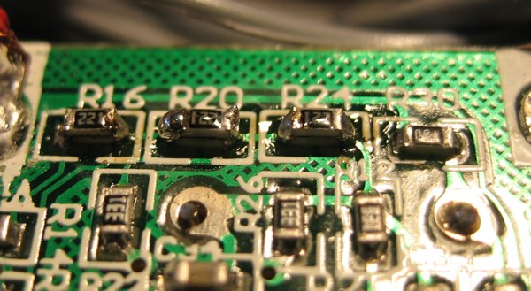
Original PAL circuit:
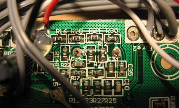
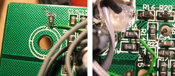
R16, R20, R24 paralleled with 220 ohm 0604 SMD resistors:
RX connects to ground using a little wire wrap:
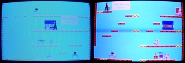
The result
To see the impact of the fix, look at the following screen shots of Impossible Mission. Left is before, right is after fixing. Note that in both pictures the "Nothing here" box is supposed to be seen. The colors talk for themselves. Thanks to Spiff for these images:
By Lars Ole Pontoppidan
Jan 2007
I hope you enjoyed this content!

Comments powered by Talkyard