The Capmeter
This is an unedited republication of the Capmeter project description as it appeared on the first Lars' Electric Endeavors website.
Lars, February 2018
Measuring capacitances with an AVR
Motivation
It is often useful to know the capacitance between conductors such as wires, PCB traces or the legs of a capacitor. Being able to measure such capacitances is a great tool to verify the value of capacitors or other components, to test cables or to analyse circuits.
It is perfectly possible to buy multimeters able to measure capacitance and to buy dedicated capacitance meters. But these devices tend to be expensive, so I decided to make one myself. Besides, the capmeter presented here has a special feature that makes it stand out from at least the more inexpensive commercial meters.
Features
The capmeter is able to measure capacitances with a resolution of 1 pF in the lower end. Max measuring capacitance is about 10000 uF. Actual measurement precision is not known, but linearity errors seems to be about 0.5 % worst case, and < 0.1% typical (measured by checking if parallel capacitors measures as the sum of each). Large electrolytes are the most problematic to measure accurately.
The meter has two ranges accessible through an auto detect mode, and modes for forcing low or high range. The meter also has two different measurement thresholds, giving two readouts for the same capacitor. This special feature enables checking if the measurement is credible and if the measured device is behaving like a capacitor should. Electrolytes will display their inherent non linearity by giving differing readouts.
The meter has a menu system that among other things allow calibration of zero offset and 1 uF. The calibration can be saved to EEPROM.
Design considerations
The measuring principle
A proven method of measuring capacitance is to form an RC network, which consists of the unknown capacitance and a known resistor. When a voltage is applied to the series connection of these components, the voltage accross the capacitor will slowly rise. Such a network is a 1. order system and is characterized by its time constant, which is when the capacitor has reached about 63% of the applied voltage. This time constant, tau, is given by the formula:
tau = RC
So, by measuring the time constant the capacitance can be calculated easily. The measurement does not have to be of the principal time constant at 63% voltage though, any other voltage threshold can be used as well, and the time will still be proportional to the capacitance, assuming everything behaves linearly.
The basic measuring principle is thus as sketched in the following diagram:
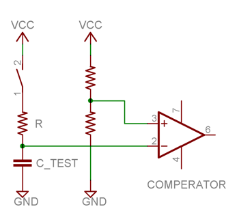
From theory to practice
The AVR microcontrollers have an IO feature which is most convenient for this task, the analog comperator. This comperator can trigger an interrupt when one voltage grows beyond another, and combining this with a timer counting every clock, the time measurement can be done with a granularity of one clockcycle. At 16 MHz this means a resolution of 65.2 nano seconds. So, the basic principle is to let the AVR apply a voltage to the RC network and measure when the capacitor voltage exceeds a certain threshold using the analog comperator.
But what should the value of the resistor be? It should be high enough to allow measuring very small capacitances, and low enough to allow measuring large capacitances in reasonable time. So it depends on the range requirement and as I wanted to be able to measure pico farads to milli farads, it became clear that two values of R was required, corresponding to low and high range.
If the measurement is simply done as just described, it must be assumed that the capacitor is indeed at 0V before the measurement starts. So the capacitor has to be discharged completely - if there is even the slightest resistance, this will theoretically take forever. Also, electrolytes tends maintain a small voltage regardless of the amount of discharging. The solution to this problem is to not assume the capacitor is at 0V and instead have two threshold voltages. The time between crossing first and second threshold is then the time measurement, and now the capacitor just has to start at a voltage below the first threshold.
The bonus feature
Having multiple threshold values is easily implemented on the AVR, thanks to the ability to configure the analog comperator to compare with the output of ADMUX, the analog multiplexer that selects a member from port A. Thus, a handfull of different threshold voltages can be wired to port A pins and selected in software with ADMUX. I decided to take advantage of this and introduced a third threshold voltage. Now multiple measurements can be made, charging time from threshold A to B, and from A to C. Scaled with their according factors, both these measurements should give the same capacitance value.
Both measurements are showed on the display, and they can be used as an indicator of how good the measurement is - sort of a double check. If they show different values, something is acting nonlinearly. It could be a sign of a bad capacitor, or it could be because other components are disturbing the measurement. If they show the same value, the capacitor is working good and the measurement is as good as it gets with the current calibration.
References
Implementation
Hardware
One of the smallest atmegas, the atmega8, was selected to do the job, as the IO and resource requirements are only limited. The power supply consists of a 9V battery linearly regulated to 5V using a 7805, to get a stable and quiet supply. The rather large 47 uF tantalum decoupling cap might be overkill, but was selected to further stabilize the power supply.
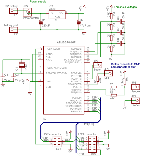
The measurement circuit needs a little explanation. The meter can be in three modes: low range measuring, high range measuring or discharging. These modes are defined by the states of PD5 and PD6. When discharging PD6 pulls low and the capacitor is discharged through R7 (220). At high range measuring PD5 pulls high, charging the capacitor through R8 (1.8K) and PD6 is high impedance to allow the analog comperator to watch the voltage. At low range measuring PD5 is also high impedance and only R6 (1.8Meg) charges the capacitor.
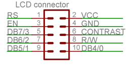
The LCD must be a standard HD44780 compatible 16x2 character display. The connector shown above is a 10 pin flat cable, with a pinout selected for ease of routing on a stripboard. The cable must connect to the LCD as follows:
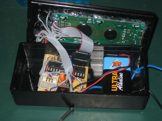
The circuit was implemented on stripboard and built into a simple plastic case. The top of the case was cut to hold the button, the LED and the LCD, which was all hot-melt glued:
Software
Beside the capacitance measurement logic and configuring the mcu's timer and analog comperator, the following more general tasks are solved by the software:
- Assembler optimized fixed point math multiplication
- EEPROM read and write functions
- Delay milliseconds function
- Conversion of numbers to ascii with decimal and decade control (pF, nF, uF, mF)
- Hold-down-single-button menu implementation
- HD44780 compatible LCD char and string routines
The software can run on atmega8 and on atmega48/88/168 family mcu's. A single line of code dealing with timer setup must be changed according to what family of mcu is used.
Download:
References
- This project gave a lot of inspiration: ELM Digital Capacitance Meter
- Spiff about using HD44780-based LCDs with AVR microcontrollers
Capmeter - in action
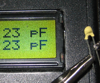
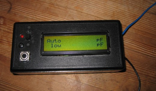
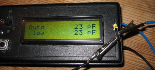
When the test leads isn't connected anything, the zero capacitance should be calibrated. When the meter shows 0 farad it looks like this:
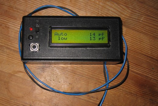
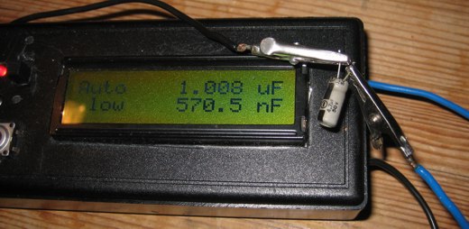
If the test leads get close to each other, the capacitance grows:
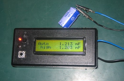
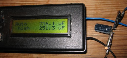
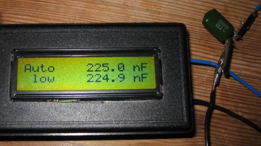
Electrolytes tends to measure somewhat higher than rated:
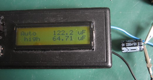
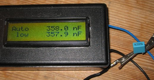
Bad electrolytes measure interesting. Notice how the should be equal readings are different:
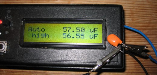
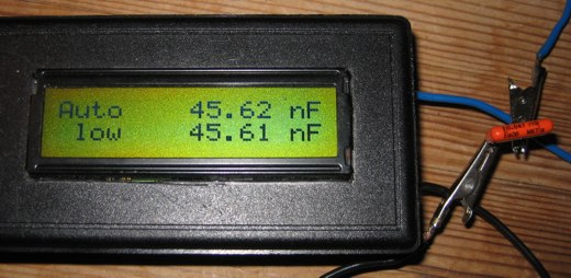
A couple of other capacitors. Notice how exactly the readings match on good quality capacitors.
By Lars Ole Pontoppidan
Hardware done: Jan 2006, article written: Nov 2006
I hope you enjoyed this content!

Comments powered by Talkyard