Electric Repair Stories
This is an unedited republication of the Electric Repair Stories series as featured on the first Lars' Electric Endeavors website. The post includes modifications such as my NAD display lighting LED mod
Lars, February 2018
In time I have repaired a number of electronic devices, mostly HiFi equipment. This article consists of logs of the most interesting repairs
NAD 2140
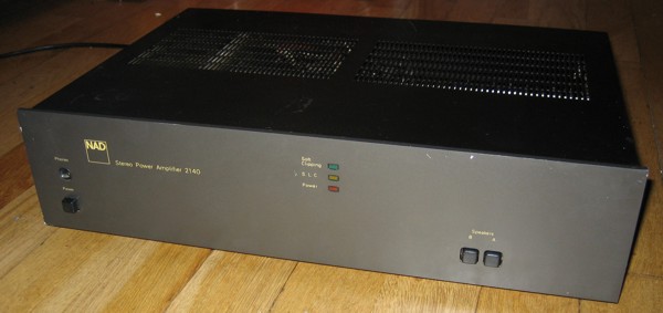
This power amplifier features the classic MJ15003 and MJ15004 power transistors in TO-3.
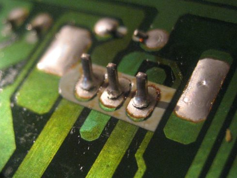
One channel appearently ok, one channel distorted. As I recall, it was one of the output stage driver transistors.
Accidentally a trimpot was shorted with the grounded heatsink during repair, which resulted in very noticeable hum in both channels... The power supply regulation circuit for the preamp was blown, resulting in nasty ripple. Changing a couple of diodes and transistors solved the problem.
Unfortunately the transformators of this amp emits some mechanical vibration. Unable to fix it completely.
By Lars Ole Pontoppidan, Aug. 2005
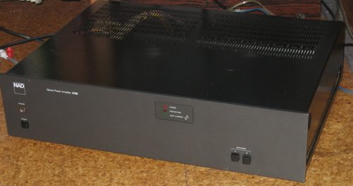
NAD 2150
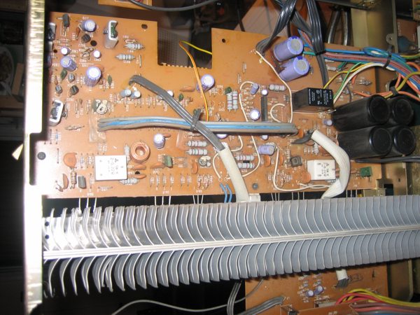
Lets take a look inside:
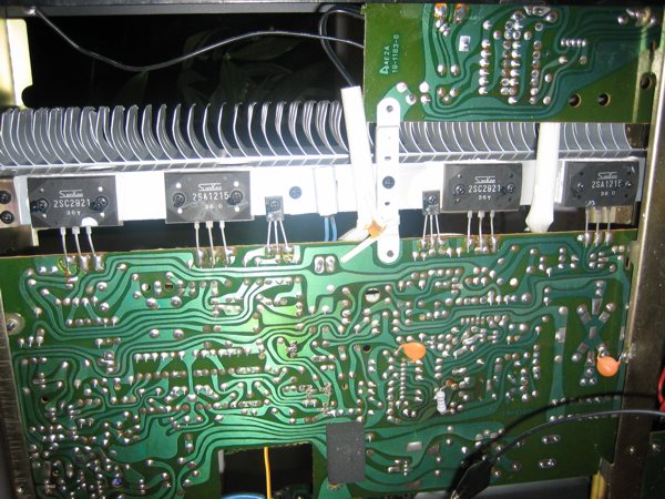
This amplifier seems to be newer and more sophisticated than NAD 2140. The power transistors are the nice and juicy Sanken 2SA1215 and 2SC2921 with a 15 A, 150 W rating. These could easily power 100W+ amplifiers. But the 50 in 2150 means that the amplifier is regarded a 50 W unit. We will see that this is a typical NAD understatement.
The protection IC TA7317P monitors the health state of the amp and controls a relay. This system also implements a soft on function, waiting a couple of seconds before turning on. The 2140 did not have this relay feature.
Problem: Protection LED never goes off, relay never clicks. Measurements showed that the power transistors in both channels had insufficient VBE, they were "off". The output stages had insufficient bias voltage. Explanation was that a certain function of the powersupply was blown, propably a current source. Q802 (a BC556) was changed and everything was OK! As this transistor gets very hot, a heatsink was attached to it.
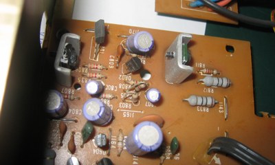
Q802 was the faulty transistor
The bias current was rather low, about 10 mA and was adjusted to about 40 mA, as a matter of personal preference.
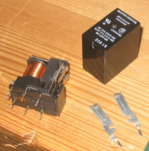
Another problem showed up. After power on, one channel seemed to have a series resistance in the output. Turning op the volume for a moment removed the resistance. The relay was the culprit. Fortunately it could be disassembled and the contact surfaces were cleaned and roughened, which fixed the problem.
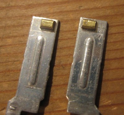
These contact surfaces clearly have seen better days
By Lars Ole Pontoppidan, Dec. 2005
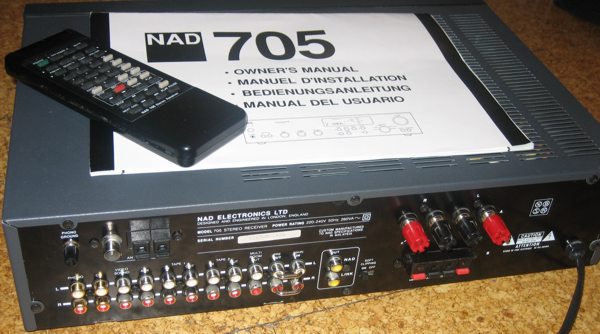
NAD 705
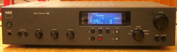
Note. Picture taken after the display light was repaired
Problem: The unit did not turn on properly, relay did not click. Light in display was bad.
The unit was in great looking shape, inside as well, which was densely packed with PCB. Searching the web for common failures for the unit, indicated that bad solders in the powersupply was a typical problem.
But there was a small problem. While you could easily access the PCB underneath the output stage, it required close to a complete disassembly to get underneath the powersupply PCB, which was kind of difficult. I almose gave up due to the amount of work required of the disassembly, not knowing if that was the problem, but luckily I decided to carry on:
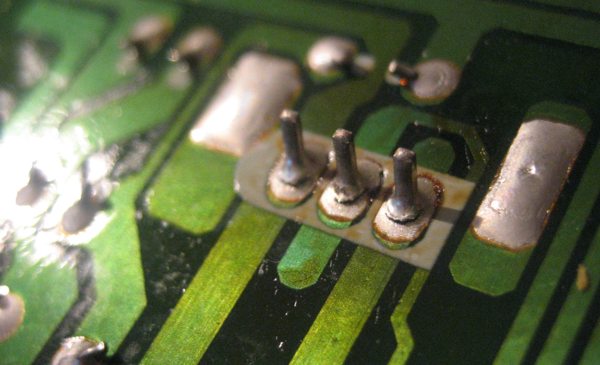
This was the worst solder of them all, belonging to a voltage regulator. I gave nearly all solders in the powersupply a fresh-up though, and checked most of the components. This cured the problem and the unit worked flawlessly.
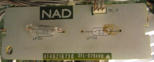
Finally, there was a cosmetic problem. The display light was uneven due to a burned out bulb. From what I could read on the net, it's a typical problem for similar NAD displays. New (original) light bulbs would burn out after a couple of years. Lacking other replacements, I dediced to give white LEDs a try instead:
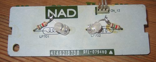
Before and after NAD display light repair/modification
After some adjustments the led light was actually very good, though more blueish in the color. The leds should survive until the end of the world, and as an extra bonus, they consume less power and generate less heat. Notice that I cut the lens of the leds to make them unfocused.
By Lars Ole Pontoppidan, Jan. 2006
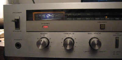
Pioneer SX-600L repair
Initially I did not have much hope for this unit, and I did not want to invest much in the repair. But the really nice retro look and feel convinced me that I was worth the trouble anyway:
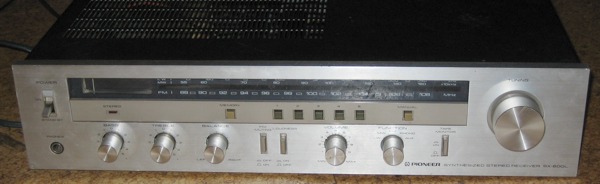
It's a synthesized reciever, which I guess means that the tuning is done by other means than a variable air capacitor, giving the possibility of memorizing frequencies.
So, whats inside?
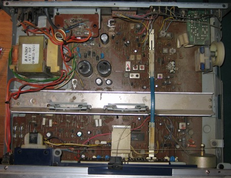
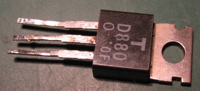
The output stage features an asymetric design with purely NPN power transistors, all 2SD880. This was done by combining a darlington and a complementary coupling for the output stage, which is not necessarily a bad design. Years back PNP transistors were inferior to NPN's and much more expensive.
There were no less than 6 fuses in the unit. And they were messed up. The previous owner seems to have been tampering with them without much luck. Some were blown, some were missing and the rest had the wrong values. Blown fuses in the supply indicate that there might have been a serious accident.
The repair
Quick examination showed that the power transistors of one output stage were gone. As I didn't want to spend time measuring every component, I just installed the correct fuses, unsoldered the output transistors and applied power cautiously with the lamp current limiter. A 25W light bulb were lit continously which is a rather bad sign, indicating that the unit shortcircuits in some way, but it could also be that there simply was too little current to get going. As I couldn't find an obvious problem in the supply, I tried the 60W bulb. It were lit for a second and hurray, it went black!
One channel was fine, replacing the power transistors of the other channel didn't bring it back. The lamp was much too bright, indicating excessive current draw... Without the limiter I might have damaged the new power transistors.
Explanation was that the drivers of the output stage were also blown: 2SA720A, 2SC1318. Actually, one of them was exploded!
And that wasn't enough, the bias transistor was also gone, a 2SC945. Replacing that as well finally brought back the right DC conditions for the power transistors, and both channels were functioning perfectly. Incredible that all five transistors of the output stage had failed at once, it might have been a spectacular short circuit.
The frequency indicator was a red LED connected to a plasic light guide. I though it was rather dim, so I replaced it. What color to select... Well I haven't used yellow for a while:
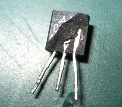
Inside the blown 2SD880
I couldn't help myself from taking a peak inside one of the blown power transistors. I have encountered this transistor model a couple of places, so I guess it have been a popular piece once. Well, probably just cheap:
Lets give it a whack:
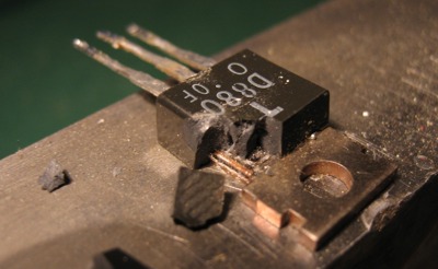
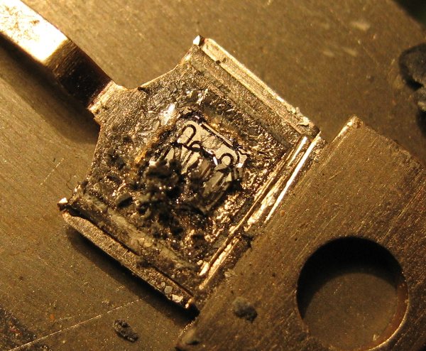
The silicium didn't survive the hammer. But you can see some of the structure and estimate the size of the die. It looks like some violent overheating killed that poor fellow.
By Lars Ole Pontoppidan, May 2006
Lamp current limiter
This is a poor man's power supply current limiter, with visual feedback.
When repairing broken stuff, its really handy to have some way of applying the main power in a limited way, to prevent further damage.
Inserting a conventional light bulb in series with the load is a clever way of achieving that, as it exploids the non-linearity of the lamp. When little current is drawn, the filament is cold and has a relatively small resistance, allowing a high voltage at the load. If a large current is drawn, the filament warms up and increases its resistance, limiting the current.
With a 60W bulb, one can be absolutely sure that no more than 60W will be applied, and definately only a lot less than that.
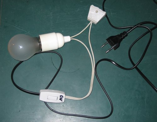
This picture shows my crude effectuation of a such current limiter.
When turning on an amplifier, there will be an inrush current for charging the power supply capacitors. This should show as a short flash, if the lamp is of a small enough rating. When the amplifier is stabilized, only a little or no light should come from the lamp. A large continous light might indicate that too much current is drawn, or it might be that the bulb's rating is too small.
I must stress that you should not do mains wiring, unless you know what you are doing. Please remember to pull the plug instead of relying on the switch before putting hands into the equipment. I will take no responsibility for any desired or undesired result this current limiter might produce.
By Lars Ole Pontoppidan, May 2006
I hope you enjoyed this content!

Comments powered by Talkyard